
 German
 Japanese
 Portuguese
 Korea
Korea
 Mexico
 Dutch
Dutch


AI Server Power Design: Tackling Efficiency, Power Density, and Thermal Challenges

Data Center Infrastructure & Power Electronics
AI Server Power Design: Tackling Efficiency, Power Density, and Thermal Challenges
A comprehensive engineering and sourcing guide to the power architectures, conversion technologies, distribution networks, cooling strategies, and validation practices behind reliable AI computing infrastructure.
AI servers transform electrical power into useful computation at an extraordinary scale. Accelerators, processors, high-bandwidth memory, networking devices, and storage all compete for a limited electrical and thermal budget. As more computing capability is concentrated into each server and rack, power delivery becomes a central architectural challenge rather than a supporting function.
The difficulty is not simply supplying more watts. AI workloads can create rapid changes in current demand, high local heat flux, uneven loading, and correlated power events across multiple devices. Meanwhile, operators expect high availability, predictable efficiency, manageable maintenance, and compatibility with existing facility infrastructure.
These requirements create three tightly connected objectives: high efficiency, to limit energy waste; high power density, to fit more capability into constrained space; and effective thermal management, to keep components within reliable operating limits. Improving one objective without considering the others can produce disappointing results.
A smaller converter may need faster switching, which increases electromagnetic interference and magnetic losses. A more efficient accelerator can still require a difficult low-voltage, high-current supply. Liquid cooling can remove substantial heat from processors while leaving power components without enough airflow. Additional redundancy can improve availability while reducing the loading—and sometimes the efficiency—of individual power supplies.
This article examines the complete design problem, from facility-facing input stages to package-level power delivery. It focuses on established engineering principles and application-dependent choices rather than prescribing one universal architecture. Numerical examples are illustrative design calculations, not specifications for a particular commercial platform.
1. Why AI Workloads Change Power Design
Conventional server power design already requires careful attention to efficiency and reliability. AI systems intensify the challenge because they combine dense parallel processing with substantial memory and communication activity. Electrical demand changes as execution units become active, memory traffic increases, or workloads move between computation and communication phases.
Average workload power is useful for energy planning, but it does not describe the worst electrical event. A regulator must handle load steps, not just steady-state current. A power shelf must support permissible overloads and transitions. A rack distribution system must tolerate realistic combinations of simultaneous demand without exceeding connector, cable, or protective-device limits.
Multiple accelerators may also respond to the same software event. Their loads are not necessarily independent, so assuming that individual peaks will always cancel out can underestimate aggregate demand. Conversely, simply adding every theoretical maximum may create an unnecessarily expensive installation. Capacity planning should use measured workload behavior and explicitly defined operating constraints.
Separate the Relevant Time Scales
- Very fast events: local decoupling and package-level power distribution must support rapid switching activity.
- Regulator-scale events: control loops, inductors, and output capacitors respond to changing rail current.
- Server- and rack-scale events: power supplies, bus capacitance, and management controls handle broader demand changes.
- Facility-scale events: UPS systems, upstream distribution, and cooling infrastructure respond over longer intervals.
These layers must work together, but they cannot substitute for one another. A rack-level software limit cannot correct a nanosecond-scale voltage disturbance. Similarly, adding package capacitors will not solve an overloaded rack feed. Good architecture assigns each requirement to the physical layer capable of meeting it.
2. Mapping the Complete Power Chain
Before selecting components, define the electrical boundary of the design. “Server efficiency” can refer to an AC power supply, a DC distribution system, or the complete path to the accelerator rails. These are different measurements and should not be compared without clarification.
A representative installation may include facility AC distribution, a UPS, rack power distribution, an AC–DC power shelf, a low-voltage DC bus, board-level intermediate conversion, and local regulators. Other systems use different boundaries, including centralized rectification, server-level supplies, or higher-voltage DC distribution.
Illustrative Electrical Path
Facility supply → rack or server AC–DC conversion → DC distribution bus → intermediate converter → point-of-load regulators → accelerator, memory, processor, and networking rails
Every stage introduces loss, cost, volume, and a control interface. Removing a stage may improve efficiency, but only if the remaining converters can achieve the required voltage ratio, isolation, transient response, and operating range without excessive compromise.
For example, a distribution voltage that is efficient for moving power across a rack may be poorly matched to direct regulation of a sub-1 V processor rail. Intermediate conversion can reduce the burden on the final regulator, even though it adds another conversion step.
Architecture reviews should identify where isolation is required, where energy is stored, how faults are interrupted, and which stages regulate voltage tightly. Cascaded converters also interact dynamically. A tightly controlled downstream converter can behave like a constant-power load over part of its operating range, making source impedance and stability important.
Document the entire chain early. Without a shared power-tree definition, teams may optimize different boundaries and unintentionally shift losses, thermal problems, or protection responsibilities onto one another.
3. Choosing Distribution Voltage
Higher distribution voltage reduces the current needed to deliver a given power. Because resistive heating depends on current squared, this can significantly reduce copper losses and ease the burden on cables, connectors, busbars, and PCB planes.
Consider an idealized 6 kW load. At 12 V, the current is 500 A. At 48 V, it is 125 A. For the same path resistance, the resistive loss at 48 V is one-sixteenth of the loss at 12 V. Real systems introduce conversion losses and voltage variation, but the distribution advantage remains important.
This is a major reason that 48 V-class distribution is attractive in high-power computing. However, “48 V” does not always mean a fixed 48.0 V operating point. Actual architectures may use different nominal setpoints and operating windows. Equipment compatibility must be based on the specified minimum, maximum, transient, and fault voltages.
| Approach | Main Advantage | Main Constraint |
|---|---|---|
| 12 V distribution | Established ecosystem and convenient input for many local regulators | Very high current at multi-kilowatt power levels |
| 48 V-class distribution | Lower distribution current and reduced copper burden | More demanding downstream conversion and fault-energy management |
| Higher-voltage DC | Further reduction in distribution current | Greater insulation, interruption, compatibility, and service-safety demands |
No voltage choice is universally optimal. Higher-voltage architectures may be attractive for specific deployments, but they require compatible converters, connectors, switching devices, protection, and maintenance procedures. Existing infrastructure can strongly influence the economic result.
Even low-voltage buses can deliver dangerous fault energy. Touch-voltage considerations do not eliminate the risk of burns, arcs, molten metal, or fire. Distribution design must address available current and protective clearing behavior, not only nominal voltage.
4. AC Input, PFC, and Power Shelves
The AC-facing stage must convert facility power efficiently while satisfying input-current, safety, electromagnetic-compatibility, and ride-through requirements. Its design depends on line voltage, phase arrangement, power rating, redundancy, and the deployment environment.
Power-factor correction, or PFC, shapes input current and regulates an internal energy bus. Active PFC architectures can provide high power factor and controlled harmonic performance, but the result must be verified across the required line and load range. High power factor is not the same as high conversion efficiency.
Interleaving can spread current across several phases, reduce selected ripple components, and distribute heat. Bridgeless or totem-pole approaches can reduce conduction losses associated with conventional rectification, but they require careful commutation, control, sensing, and EMI design.
Isolation and Output Regulation
A downstream isolated conversion stage commonly provides the required output voltage and electrical separation. Resonant and phase-shifted bridge architectures are among the available choices. The best topology depends on power level, operating range, regulation needs, magnetics, and soft-switching behavior.
Efficiency at nominal input is insufficient for qualification. Lower line voltage can increase input current and conduction losses. High ambient temperature may reduce allowable power. Frequency variation, distorted input, and source impedance may also matter in the intended facility.
Hold-Up and Modular Operation
Hold-up energy helps bridge specified input interruptions, but it requires storage volume and careful management of the internal bus range. A system-level UPS does not automatically remove every local ride-through requirement. The permitted interruption and recovery behavior must be defined explicitly.
Power shelves must also handle current sharing, module insertion, module removal, and a failed supply without destabilizing the DC bus. Efficiency should be evaluated under the actual redundancy policy, because a bank of lightly loaded modules can behave differently from one supply operating near its optimum load.
5. Intermediate DC–DC Conversion
Intermediate conversion bridges the gap between an efficient distribution voltage and the needs of local regulators. In a 48 V-class architecture, an intermediate bus converter may create a lower-voltage rail that feeds multiple point-of-load stages.
This stage can be regulated, loosely regulated, or based on a relatively fixed conversion ratio, depending on the architecture. An unregulated or fixed-ratio approach may achieve favorable efficiency and density, but downstream regulators must tolerate the resulting input variation.
Wide conversion ratios are challenging. Attempting to convert directly from a rack distribution bus to a very low processor voltage can create extreme duty-cycle requirements and difficult current handling in a conventional buck architecture. Alternative switched-capacitor, resonant, hybrid, or transformer-based structures can help, but each introduces its own operating constraints.
Choosing Where to Place Conversion
Centralized intermediate converters can simplify some mechanical arrangements and consolidate cooling. Distributed converters can shorten high-current paths and improve local flexibility. The correct balance depends on board area, bus impedance, service boundaries, fault containment, and load placement.
Conversion should generally occur close enough to the load to avoid moving unnecessarily high current over long distances. However, placing a converter next to an accelerator may expose it to a hotter environment and compete with memory, signal routing, or cooling hardware.
Control interaction also requires attention. Input filters, bus capacitance, cable inductance, and downstream constant-power behavior can produce oscillation if source and load dynamics are poorly matched. Stability analysis should include realistic impedance models rather than only standalone converter simulations.
Finally, consider sequencing and pre-bias. An intermediate rail may remain energized from another source or decay slowly during shutdown. Converters must start, stop, and recover predictably under those conditions without reverse-current surprises or violations of downstream rail requirements.
6. Point-of-Load Regulation and Transients
The final conversion stage supplies the low-voltage rails used by accelerators and processors. At these voltages, current becomes extremely large. As an illustration, supplying 1 kW at 0.8 V requires 1,250 A at the load. The actual distribution among rails depends on the device architecture, but the example shows why local power delivery is difficult.
Multiphase regulators divide current among several switching phases. Interleaving can reduce selected ripple components, distribute heat, and improve dynamic behavior. More phases also introduce additional components, current-sense channels, gate-drive loss, control complexity, and layout demands.
Phase count should be selected from hot current capability, transient requirements, efficiency across load, and cooling conditions. Phase shedding can improve light-load performance, but transitions into and out of reduced-phase operation must remain stable and meet the rail specification.
Transient Response Is a Distributed Problem
When load current increases, the regulator cannot instantaneously raise inductor current. Local capacitance initially supplies the difference. Voltage deviation depends on capacitor charge depletion, equivalent series resistance, equivalent series inductance, and the impedance of the path to the load.
For an idealized example, sustaining an additional 200 A for 2 microseconds with only 20 mV of capacitive droop would require 20 millifarads of effective capacitance. That calculation excludes parasitic effects and assumes the regulator contributes none of the incremental current during the interval. It illustrates why response time and local impedance matter—not a universal capacitor recommendation.
Remote sensing can compensate for steady-state path drop, but it cannot eliminate inductance or recover voltage instantaneously. Load-line control may intentionally allow a specified voltage change with current, improving transient management within the processor’s permitted operating envelope.
The board, package, and on-die decoupling form a single power-delivery network. Their interaction must be evaluated across frequency. Adding capacitance indiscriminately can introduce anti-resonances or move a problem rather than solve it.
7. Measuring and Improving Efficiency
Efficiency must be reported with a defined measurement boundary. An AC–DC supply’s efficiency does not include every downstream regulator. Likewise, rack-level efficiency may exclude facility cooling or UPS losses. Clear boundaries prevent misleading comparisons.
Losses compound across cascaded stages. If three conversion stages operate at 97%, 98%, and 92% efficiency, their combined efficiency is approximately 87.5%, before any additional distribution losses. Improving the weakest stage can therefore matter as much as refining an already efficient front end.
Small Percentage Changes Can Remove Significant Heat
At a constant 10 kW DC output, a converter operating at 96% efficiency dissipates approximately 417 W. At 97% efficiency, its loss falls to approximately 309 W. A one-percentage-point efficiency improvement therefore removes about 107 W of heat at that operating point.
If that output and efficiency difference were maintained continuously for a full year, the direct electrical saving would be about 941 kWh, excluding any cooling-system benefit. Real annual savings must use the actual load profile, operating hours, input conditions, and temperature dependence.
Build a Loss Budget
- Semiconductor conduction, switching, and gate-drive losses.
- Transformer and inductor core and winding losses.
- Capacitor ripple-current heating and balancing losses.
- Busbar, cable, connector, and PCB resistance.
- Control electronics, isolated supplies, fans, and other auxiliaries.
Measure at multiple loads rather than highlighting a single peak. Redundant operation, idle periods, inference duty cycles, and changing workloads can make partial-load performance commercially important.
Efficiency certifications can support procurement, but they do not replace application-specific testing. Verify the relevant input configuration and test conditions, and distinguish conversion efficiency from useful computation per unit energy. A power-efficient server that is poorly utilized may still deliver disappointing operational value.
8. Selecting Silicon, GaN, and SiC
AI server power systems contain several voltage domains, so one semiconductor technology rarely represents the best choice everywhere. Selection should be performed stage by stage using realistic loss, thermal, reliability, and cost models.
Silicon MOSFETs remain highly competitive in many low-voltage, high-current stages. Their mature ecosystem, low on-resistance, packaging options, and cost can make them attractive for point-of-load conversion and synchronous rectification.
GaN transistors can be compelling in high-frequency stages where low switching-related charge and favorable commutation behavior enable better efficiency or smaller magnetics. They are relevant to suitable PFC, isolated conversion, and intermediate-bus applications.
SiC devices can be attractive in higher-voltage or high-power front ends, depending on topology and deployment requirements. Their availability in higher blocking-voltage classes and suitable packages can simplify some demanding architectures.
Avoid Headline-Parameter Selection
Low room-temperature on-resistance does not guarantee low total loss. Evaluate resistance at operating temperature, switching energy under comparable conditions, output-capacitance behavior, reverse conduction, and gate-drive demand.
GaN’s fast transitions require disciplined gate-drive and layout design. SiC also requires appropriate gate voltage, transient control, and fault protection. Neither technology should be inserted into a silicon design without checking driver compatibility, overshoot, EMI, thermal paths, and safe operating limits.
Soft-switching topologies change the comparison but do not eliminate device-dependent losses. Light-load operation, startup, and transients may leave the preferred soft-switching region. Reverse conduction and capacitance-related energy still matter.
A mixed-technology design is often reasonable. The objective is not to maximize the number of wide-bandgap devices, but to achieve the best verified system outcome. Qualification evidence, supplier support, package availability, and second-source implications should be considered alongside electrical performance.
9. Magnetics and Capacitor Design
Power semiconductors receive much of the attention, but magnetics and capacitors frequently determine the size, temperature, lifetime, and cost of a converter. Their optimization must accompany any increase in switching frequency.
Transformers and Inductors
Higher frequency can reduce the magnetic size needed for a given conversion task, but core loss, skin effect, and proximity effect become increasingly important. Winding arrangement influences leakage inductance, capacitance, insulation, and thermal resistance.
Planar magnetics can support low-profile assembly and controlled geometry, but they do not automatically deliver lower loss. PCB winding resistance, current crowding, interlayer capacitance, and hotspot location require evaluation. Integrated magnetics may save space while coupling thermal and electrical constraints more tightly.
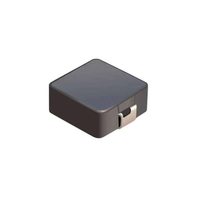
For multiphase regulators, inductors must tolerate peak current, ripple, temperature, and transient conditions without unacceptable saturation or loss. Coupled-inductor approaches can offer benefits in appropriate designs, but their control behavior and manufacturing tolerances must be understood.
Capacitance Means More Than Nominal Microfarads
Different capacitor technologies serve different frequency and energy-storage requirements. Bulk capacitors provide hold-up or bus support; polymer and ceramic capacitors can improve local dynamic behavior. The effective value of some ceramic capacitors falls significantly under DC bias, so nominal capacitance can overstate available performance.
Ripple-current heating, equivalent series resistance, equivalent series inductance, temperature, and expected lifetime all matter. Parallel capacitor banks also interact with interconnect inductance and converter control loops.
Mechanical reliability deserves attention. Large ceramic components can be vulnerable to board strain, while heavy magnetic components can require additional support. Production soldering, vibration, handling, and thermal cycling should be included in qualification. A compact design that is difficult to assemble consistently is not a successful density improvement.
10. Busbars, Connectors, and PCB Power Delivery
High-current distribution can become the limiting factor even when conversion efficiency is excellent. Small resistances create voltage drop and localized heat, especially at connectors, bolted joints, vias, and narrow PCB transitions.
At 500 A, a connection resistance of only 100 micro-ohms dissipates 25 W. That heat is concentrated around a small physical region and may increase resistance further as temperature rises. Contact quality, mounting force, plating, contamination, and mechanical aging therefore have direct electrical consequences.
Busbars can provide a low-resistance distribution path and controlled mechanical structure. Laminated arrangements can also reduce selected loop inductances. Their design must consider insulation, edge clearances, joint accessibility, thermal expansion, and fault forces.
Connectors Need Application-Level Qualification
A connector’s headline current rating depends on test conditions, contact count, ambient temperature, and allowable temperature rise. Real assemblies may have uneven sharing among contacts or less favorable cooling. Mating cycles, vibration, insertion alignment, and partial engagement must also be considered.
Hot-plug capability is a separate requirement from continuous-current capability. The system may need precharge, sequenced contacts, controlled insertion current, and measures to prevent arcing. Do not assume that a high-current connector is suitable for live insertion.
PCB and Package Paths
Within the server, copper thickness, plane shape, via arrays, layer transitions, and regulator placement influence both resistance and inductance. Routing a low-voltage rail over a longer distance can consume valuable voltage margin and worsen transient behavior.
Package-aware or vertical power-delivery approaches can shorten the high-current path in suitable platforms. However, they introduce mechanical, cooling, assembly, and serviceability requirements of their own. The electrical benefit should be verified within the actual processor package and board ecosystem rather than assumed from geometry alone.
11. The Real Meaning of Power Density
Power density is often expressed as output power per unit volume. That metric is useful only when the volume boundary and operating conditions are clear. A converter measured without its heatsink, filter, connectors, or cooling clearance cannot be compared directly with a complete field-ready assembly.
Continuous output capability matters more than a short-duration peak for most infrastructure planning. A compact supply that reaches its advertised rating only under unusually cold inlet conditions may require significant derating in deployment.
Higher density can be achieved through faster switching, integrated power stages, optimized magnetics, improved thermal interfaces, and three-dimensional packaging. Each method may transfer difficulty elsewhere. Dense placement can increase thermal coupling, reduce inspection access, or make component replacement impractical.
Useful Density Includes Operational Constraints
- Maximum inlet-air or coolant temperature at rated continuous output.
- Required airflow, pressure drop, coolant flow, or cold-plate area.
- Efficiency and hotspot temperatures across the load range.
- EMI filters, insulation spacing, connectors, and cable bend radius.
- Redundancy, replacement access, and mechanical retention.
At rack level, higher electrical density may be limited by facility feeds or available cooling rather than the dimensions of the power shelf. Increasing watts per rack without checking upstream capacity can create stranded compute capability that cannot be operated simultaneously.
The best optimization target is therefore usable compute capacity within the available electrical, thermal, mechanical, and maintenance envelope. Component density supports that objective, but it is not a substitute for it.
12. Air Cooling, Liquid Cooling, and Hotspots
Nearly all electrical power entering operating server electronics ultimately becomes heat within the computing environment. Efficient conversion reduces unnecessary heat, but the useful computation itself still creates a substantial cooling load. Power and thermal teams must therefore share a common operating envelope.
Air Cooling Remains a System-Level Constraint
Air-cooled power supplies depend on inlet temperature, airflow, pressure drop, dust accumulation, altitude, and fan performance. Dense fin structures may improve heat transfer locally while demanding more fan power. Recirculation can make component inlet temperatures much higher than the room sensor indicates.
Cooling should be validated in the actual chassis or rack airflow path. A supply tested alone on a bench may receive less air after installation because of neighboring modules, cable bundles, or filter restrictions.
Liquid Cooling Does Not Automatically Cool Every Component
Direct-to-chip liquid cooling can remove substantial heat from accelerators and processors, but power regulators, memory, connectors, and power shelves may remain air cooled. Reducing chassis airflow after installing cold plates can unintentionally overheat these secondary components.
Some systems extend liquid cooling to power electronics or use hybrid arrangements. The decision depends on heat flux, mechanical layout, coolant compatibility, leak management, service procedures, and the cost of maintaining reliable thermal contact.
Coolant Flow Must Match the Actual Heat Load
As an idealized heat-balance example, removing 60 kW with water and a 10°C temperature rise requires approximately 1.44 kg of water per second, or roughly 86 liters per minute near ordinary operating temperatures. This excludes design margin and assumes the full 60 kW transfers into that loop.
Actual requirements depend on coolant properties, allowable temperature rise, cold-plate resistance, flow distribution, and heat-exchanger performance. Glycol mixtures and other fluids have different properties. Pump capability must also overcome pressure drop; a sufficient nominal flow rating does not establish adequate flow through every branch.
Coolant supply temperature should be coordinated with dew point to avoid condensation. Leak detection, corrosion control, filtration, material compatibility, and service isolation are essential. Thermal qualification should include degraded flow and cooling failure, with controlled power reduction or shutdown before component limits are exceeded.
13. Protection, Redundancy, and Availability
AI infrastructure can contain enormous fault energy even at relatively low bus voltage. Protection must isolate failures quickly enough to prevent damage while avoiding unnecessary shutdown of healthy equipment.
Required functions may include overcurrent, short-circuit, overvoltage, undervoltage, overtemperature, reverse-current, and ground-fault protection, depending on the architecture. Protection thresholds should account for valid transients and tolerances without becoming so permissive that fault energy exceeds component capability.
Coordinate Protection Across Layers
A board-level short should ideally be cleared locally rather than collapsing the entire rack bus. Achieving this requires selective coordination among electronic protection, fuses, breakers, current-limited converters, and stored energy.
Available fault current and energy vary with cable length, bus capacitance, module count, and upstream source behavior. A converter entering current limit can also alter how a downstream fuse operates. Protection must be tested as a system rather than assembled from independent datasheet assumptions.
Redundancy Is More Than an Extra Module
An N+1 arrangement can tolerate one defined module failure only if the remaining modules support the required load under actual line and thermal conditions. Their transient response must also handle the sudden redistribution of current.
Dual feeds do not guarantee independence if they share an upstream source, controller, connector, or cooling dependency. Common-mode failures should be identified explicitly. ORing or reverse-blocking functions must prevent a failed source from pulling down the healthy bus.
Hot-swap testing should cover insertion, extraction, contact bounce, precharge, and management communication. A module that shares current correctly in steady state may still disturb the bus during insertion.
Finally, define the intended recovery behavior. Automatic retry can be useful for temporary faults but dangerous for persistent shorts or intermittent connections. Fault logging, latch-off policy, and service instructions should support safe diagnosis and controlled restoration.
14. Telemetry and Power-Aware Control
Modern power systems benefit from visibility into voltage, current, temperature, fan speed, fault status, and operating history. Digital interfaces, including PMBus where supported, can help expose these measurements to server or rack management.
Telemetry is only useful when its limitations are understood. Accuracy, calibration, sample rate, filtering, latency, and timestamp alignment determine what conclusions can be drawn. A slowly updated power reading cannot characterize a fast load transient.
Control Belongs at Multiple Levels
Fast analog or digital regulator loops maintain local rail behavior. Hardware protection handles urgent faults. Firmware coordinates sequencing, module operation, and thermal response. Higher-level management allocates power budgets and may adjust workload placement or operating limits.
These layers should have clear authority and fallback behavior. Loss of a management link must not disable essential electrical protection. Similarly, a software power cap should not be treated as a substitute for appropriately rated conductors and protective devices.
Rack-level coordination can reduce the chance that multiple systems exceed a shared feed or cooling limit. However, responses must be stable and predictable. Poorly tuned controls can oscillate between throttling and recovery or repeatedly transfer stress from one subsystem to another.
Use Data to Support Maintenance
Trends in temperature, voltage drop, fan demand, and current sharing can reveal developing problems. An increasing connector temperature at similar load may justify inspection, while a change in supply balance may indicate calibration drift or a degraded module.
Such signals are indicators, not automatic diagnoses. Maintenance decisions should consider sensor reliability and operating context. Firmware updates, configuration changes, and management access also require controlled processes because they can affect power availability and system protection.
15. EMI, Grounding, and Safety
High switching speed, large current, and dense packaging create a demanding electromagnetic environment. Conducted and radiated emissions depend on the entire assembly: switching loops, filters, cables, chassis bonds, heat spreaders, and parasitic capacitances.
Reducing differential-mode ripple does not necessarily solve common-mode noise. A fast switch node can drive current through transformer capacitance, heatsinks, cold plates, or chassis coupling. Liquid-cooling hardware can change parasitic paths and should be included in the installed configuration during testing.
Good layout minimizes high-frequency commutation loops, controls gate-return paths, and keeps sensitive sensing away from noisy nodes. Filtering must be designed with source and load impedance in mind. Adding a larger filter without stability analysis can create a new electrical problem.
Grounding Requires a Defined Strategy
Protective earth, chassis bonding, signal reference, and DC return serve different purposes. Their relationships should be documented rather than left to accidental mechanical contact. High-current return paths should not corrupt voltage sensing or management communication.
Isolation ratings, creepage, clearance, touch-current limits, and protective bonding depend on the product category and deployment conditions. Requirements can change with altitude, pollution degree, working voltage, and the adopted standard edition.
For ICT equipment, standards such as IEC/UL 62368-1 may be relevant, while regional EMC and installation requirements must also be assessed. Applicability should be confirmed with a qualified compliance team or test laboratory; a certified component does not automatically make the assembled server compliant.
Perform early pre-compliance testing. Discovering emissions or insulation problems after the enclosure, magnetics, and cooling assembly are frozen can force expensive redesign. Testing should include representative cables, grounding arrangements, module populations, and operating modes.
16. Validation and Qualification
A successful prototype demonstrates feasibility, not production readiness. Qualification must establish that the design works across component variation, environmental limits, operating modes, and credible faults.
Begin with a requirements matrix linking each electrical and thermal limit to a test method and acceptance criterion. This prevents important conditions from being overlooked and makes supplier claims easier to evaluate.
| Category | Representative Checks |
|---|---|
| Steady-state performance | Efficiency, regulation, ripple, power factor, current sharing, and thermal limits. |
| Dynamic behavior | Load steps, workload transitions, startup, shutdown, sequencing, and bus interaction. |
| Availability and faults | Module loss, hot swap, input interruption, shorts, sensor failure, and cooling loss. |
| Environmental reliability | Temperature variation, humidity, vibration, thermal cycling, and relevant contamination exposure. |
| Production consistency | Component tolerances, firmware configuration, assembly variation, calibration, and end-of-line coverage. |
Electronic loads are useful but may not reproduce the spatial distribution, speed, or coordination of accelerator demand. Combine programmable load testing with representative computing workloads and application-specific transient specifications.
Measurement technique is equally important. Probe inductance can create apparent ringing, sensor bandwidth can hide current peaks, and timing errors can distort switching-loss estimates. Use suitable instrumentation, documented uncertainty, and consistent thermal boundary conditions.
Finally, preserve traceability among hardware revision, firmware, component lots, test setup, and results. A passing result on one prototype configuration cannot be assumed to cover an undocumented production change.
17. Supplier Selection and Lifecycle Economics
For international equipment manufacturers and infrastructure buyers, power-system selection is both an engineering decision and a supply-chain commitment. Unit price is important, but so are qualification evidence, delivery reliability, technical support, and change control.
Request specifications for the exact model and configuration. Confirm rated power at the intended input voltage and temperature, allowable overloads, cooling requirements, output window, communication behavior, and redundancy compatibility.
Questions to Ask a Power-System Supplier
- Are efficiency curves available across input voltage, load, and temperature?
- Which cooling conditions are required for continuous rated output?
- How are current sharing, hot swap, precharge, and reverse blocking implemented?
- What are the protection thresholds, timing, recovery modes, and tolerances?
- Which safety and EMC reports apply to the exact product configuration?
- What traceability, change notification, failure analysis, and lifecycle support are provided?
- Are alternative modules electrically, mechanically, and digitally compatible?
Second sourcing requires more than matching voltage and wattage. Connector pinouts, management commands, current-sharing methods, airflow direction, startup timing, and fault behavior can differ. Substitution may require requalification even when the mechanical dimensions match.
Lifecycle cost should include energy, cooling, spare inventory, maintenance labor, downtime exposure, and integration engineering. A lower-priced module may become more expensive if it needs additional cooling or creates service complexity.
Likewise, environmental claims should use realistic operating assumptions. Higher conversion efficiency can reduce use-phase energy, but lifetime, repairability, material use, and replacement rates also matter. Procurement decisions are strongest when commercial terms and technical acceptance criteria are defined together.
18. A Practical Design Framework
An effective development process starts with system requirements and progressively reduces uncertainty. It does not begin by selecting a fashionable switching device or maximizing a converter’s headline density.
Step 1: Define the Deployment Envelope
Document facility input, rack power budget, workload profiles, cooling conditions, redundancy targets, service access, lifetime, and compliance requirements. Identify which limits are fixed and which can be negotiated.
Step 2: Build the Electrical and Thermal Architecture Together
Select distribution voltage, conversion stages, regulator placement, and cooling paths as a coordinated system. Include cables, connectors, cold plates, fans, and maintenance boundaries from the beginning.
Step 3: Establish Loss and Impedance Budgets
Allocate efficiency targets across stages and voltage-deviation limits across the power-delivery network. Model steady-state operation, transient demand, source-load interaction, and worst-case temperature.
Step 4: Prototype the Highest-Risk Interfaces
Test high-current connections, regulator transients, power-shelf sharing, and thermal interfaces early. Resolve feasibility issues before mechanical and PCB designs become expensive to change.
Step 5: Qualify the Complete Operating System
Validate representative workloads, redundancy loss, cooling degradation, management failures, and production tolerances. Confirm supply continuity and service procedures before release.
The Bottom Line
AI server power design is a coordinated optimization of conversion efficiency, distribution impedance, transient response, thermal removal, and operational resilience.
The best architecture is not necessarily the one with the highest switching frequency or smallest power module. It is the one that delivers reliable computing performance within the real electrical, thermal, manufacturing, and lifecycle constraints of the deployment.
Frequently Asked Questions
Five practical answers for server engineers, equipment manufacturers, and data-center sourcing teams.
1. Why is 48 V-class distribution attractive for AI servers?
It reduces the current needed to deliver a given power compared with 12 V distribution. Lower current can reduce resistive losses and ease the size and temperature constraints of cables, connectors, busbars, and PCB conductors. However, the system still needs suitable downstream conversion, protection, and hot-plug control. Actual bus-voltage windows vary, so compatibility must be checked using the complete voltage specification rather than the “48 V” label alone.
2. Does liquid cooling eliminate the need for airflow inside an AI server?
Usually not. Direct-to-chip cold plates may cool accelerators and processors while leaving regulators, memory, connectors, storage, and power supplies dependent on airflow. Reducing fan speed without checking these components can create hidden hotspots. Some systems extend liquid cooling to additional components, but the required approach depends on the complete thermal map. Validate component temperatures in the installed configuration, including degraded-flow and cooling-failure conditions.
3. Are GaN devices always the best choice for AI server power supplies?
No. GaN can provide valuable switching-performance and density benefits in suitable stages, but the optimum choice depends on voltage, topology, frequency, cooling, protection, and cost. Silicon remains highly competitive in many low-voltage, high-current regulators, while SiC may suit certain higher-voltage or high-power front ends. Evaluate each conversion stage separately and compare complete implementations, including gate drivers, magnetics, EMI filtering, thermal interfaces, and qualification requirements.
4. Why can an AI server fail during a load transient even when average power is below its rating?
Average power does not describe instantaneous current demand or power-delivery impedance. A rapid load step can create voltage droop before the regulator increases output current. Package inductance, PCB resistance, insufficient effective capacitance, or poor control-loop response can push a rail outside its permitted range. At higher levels, simultaneous device activity can disturb the shared bus. Validation must cover load-step magnitude, rise time, repetition, and coordination—not only steady-state wattage.
5. What should buyers verify before approving an AI server power solution?
Verify continuous output at the intended input and cooling conditions, efficiency across realistic loads, transient performance, current sharing, fault protection, and redundancy behavior. Request applicable safety and EMC evidence, management-interface documentation, traceability, and lifecycle support. Confirm that supplier alternatives are genuinely compatible and that hot-swap and fault recovery have been tested at system level. Approval should combine technical validation with delivery commitments, change-control terms, and a clear service strategy.









.png?x-oss-process=image/format,webp/resize,h_32)


