
 German
 Japanese
 Portuguese
 Korea
Korea
 Mexico
 Dutch
Dutch


PTC Resettable Fuses: Principles, Symbols, Selection, Application Notes, SMD Types, Bourns Series and Polymer PTC Deep Dive

Table of Contents
PTC Resettable Fuses Overview
A PTC (Positive Temperature Coefficient) resettable fuse is a reusable overcurrent and overtemperature protection device that automatically resets after a fault without requiring replacement. It is primarily classified into polymer types (PPTC) and ceramic types (CPTC). Due to its self-resetting properties, it is widely used across various circuits, improving product reliability and reducing maintenance costs.
⚙️ Working Principle
Under normal current, the component stays cool and the internal polymer remains in a crystalline state. Conductive particles are tightly packed, forming a low-resistance path (ohmic level) with minimal circuit impact.
During overload or short circuit, self-heating causes the polymer matrix to expand, interrupting the conductive path. Resistance surges to the megohm range, providing effective power disconnection protection.
After the fault is cleared, the component cools, the polymer contracts, the conductive path reforms, and the device automatically returns to its low-resistance state.
📝 Key Parameters
| Parameter | Description |
|---|---|
| Holding Current (Ihold) | Maximum current the PTC can reliably handle without tripping at a specified temperature. |
| Trip Current (Itrip) | Minimum current required to cause the PTC to enter a high-resistance state. Generally 1.2–2× Ihold. |
| Maximum Voltage (Vmax) | Highest voltage the PTC can safely withstand in the open-circuit state. Must exceed circuit operating voltage. |
| Maximum Interrupting Current (Imax) | Maximum fault current the PTC can safely interrupt without damage at rated voltage. |
📋 Selection Guidelines
- Determine circuit parameters: record Vmax, maximum normal operating current, maximum ambient temperature, and maximum fault current (Imax).
- Select package and voltage rating: choose SMD or through-hole based on PCB space; ensure the PTC's Vmax exceeds the circuit operating voltage.
- Match Ihold with temperature derating: consult the manufacturer's derating curve. Example: if normal current is 1 A at 25°C and max ambient is 60°C with a 60% derating factor, required Ihold = 1 A ÷ 60% ≈ 1.67 A.
- Verify response time: confirm that at the expected fault current, the PTC's response time is faster than the protected circuit's safety tolerance.
🔧 Typical Applications
🏭 Major Brands and Series
| Brand | Core Series / Features | Package Types | Current / Voltage Range |
|---|---|---|---|
| Littelfuse | Polyswitch Series — industry benchmark | Through-hole, SMD, chip | 0.05 A–14 A / 6 V–600 V |
| Bourns | Multifuse® Series — high-voltage/high-temperature | Primarily SMD, miniaturized | See Bourns section |
| Eaton (Bussmann) | Low resistance, fast response | SMD (e.g., PTSLR1210) | — |
| Fuzetec | 12 major series, ultra-wide range | Through-hole, SMD, battery, toroidal | 0.05 A–375 A / 6 V–600 V |
| TLC | Ultra-small package (0402), ultra-low resistance | SMD (0402, 0603+), through-hole | 0.05 A–5 A / 6 V–60 V |
| LUTE Technology | Miniaturized, high-reliability (sensors) | Small SMD (e.g., 0603) | 0.05 A–0.2 A / 24 V–36 V |
PTC Resettable Fuse Schematic Symbol
Diagrams related to PTC resettable fuses fall into four main categories: schematic/structural diagrams, characteristic curve diagrams, circuit symbol diagrams, and physical packaging diagrams.
🔬 Structural and Principle Diagrams
| Diagram Type | Description |
|---|---|
| Internal Structure — Low-Resistance State | Shows the PTC at room temperature: polymer in crystalline state, conductive particles tightly bound in chain-like pathways, resulting in low resistance. |
| Internal Structure — High-Resistance State | Shows the triggered state: polymer melts and expands under heat, conductive particles separate, pathways are severed, and the device enters a high-resistance protective state. |
| Dynamic Process Diagram | Illustrates the transition between conductive and protective states, and the return to normal upon cooling. |
📈 Key Characteristic Curves
| Curve Type | Description |
|---|---|
| R-T Curve (Resistance-Temperature) | Core PTC characteristic: resistance rises sharply as temperature increases. The Curie point (~130°C) is the critical trigger temperature. |
| I-T Trip/Hold Zone Diagram | Shows trip and hold current at different ambient temperatures. Zone A = trip/protection region; Zone B = normal operation region. Key basis for selection. |
| Activation Time-Current Curve | Estimates time required to trigger protection after overcurrent. Higher overcurrent = shorter activation time. |
| Resistance Recovery Curve | Shows that after fault clearance, the PTC requires a cooling period before resistance gradually recovers toward its initial value. |
🧑💻 Circuit Symbol and Basic Connection
| Diagram Type | Description |
|---|---|
| Circuit Schematic Symbol | Standard PTC symbol: a resistor symbol overlaid with a slash, labeled "PTC" or "F" to distinguish it from a one-time fuse. |
| Basic Application Connection | PTCs are connected in series within the protected circuit — identical to standard fuse placement — so that when the PTC enters high-resistance state, the current path is immediately interrupted. |
📦 Physical Form and Package Diagrams
| Package Type | Description |
|---|---|
| SMD vs. Radial Lead (RLD) | SMD: suitable for automated production and high-density PCB layouts. RLD (through-hole): suitable for high-power applications. |
| Metal-Sheet PTC | Used in industrial or automotive applications demanding higher reliability and heat dissipation. |
| PCB Pad Diagram | Detailed pad design diagrams for SMD types ensure correct and reliable soldering onto the PCB. |
PTC Resettable Fuse Symbol
There is no single globally unified standard for the PTC resettable fuse circuit symbol. Representation varies across standards and EDA software, but two common forms are widely used.
✍️ Common Symbol Notations
| Type | Symbol | Features and Description | Typical Use |
|---|---|---|---|
| Standard Fuse Symbol + Text Label | ⏛ + "PTC" | Traditional rectangular box with wavy line, clearly labeled "PTC" or "Resettable" next to the symbol or in the BOM. | Designs that do not specify a dedicated symbol but require clear functional identification. |
| IEC-Derived Thermistor Notation | PTC (variable resistor style) | Resistor symbol with a diagonal or parallel arrow, intuitively illustrating resistance varying with temperature (positive coefficient). | Very common where the thermistor nature must be directly conveyed. |
📝 Text Labels and Reference Designators
- Reference designator: PTC resettable fuses typically use "F" (e.g., F1, F2) following the IEEE 315 standard convention for fuses.
- Parameter annotations: key parameters — Ihold and Vmax — must be clearly indicated on the drawing for proper selection and verification.
📐 Drawing and Specification Guidelines
- Prioritize international standards such as IEC 60617 (equivalent to GB/T 4728) or IEEE 315 for professionalism and cross-team compatibility.
- Ensure all lines and annotations are clear to avoid confusion with variable resistors or varistors.
PTC Resettable Fuse Tutorial
PTC resettable fuses — more precisely referred to as Polymeric Positive Temperature Coefficient (PPTC) self-resetting fuses — are composed of a polymer resin matrix mixed with conductive carbon black particles. Their behavior resembles a smart switch that "expands when hot and contracts when cold."
🛡️ Working Principle
- Normal state (low resistance): at room temperature, the crystalline polymer contracts, keeping carbon black particles in close contact and forming a stable low-resistance conductive path.
- Overcurrent/overtemperature state (triggered): Joule heating (I²R) raises the temperature to the switching point (typically 85–125°C), causing the polymer to undergo a phase transition and rapidly expand. This breaks the conductive carbon black chains, driving resistance to surge dramatically and effectively limiting or interrupting current.
- Recovery state (auto-reset): once the fault is cleared, the PPTC cools, the polymer recrystallizes and contracts, carbon black particles reconnect, and the device returns to its low-resistance state.
📊 Key Parameter Reference Table
| Parameter | Symbol | Importance | Explanation |
|---|---|---|---|
| Holding Current | Ihold (A) | ⭐⭐⭐ | Maximum current the PPTC can handle continuously without triggering at a specified temperature (typically 25°C). Normal load current must stay below this value. |
| Trip Current | Itrip (A) | ⭐⭐⭐ | Minimum current to trigger high-resistance protection. Typically 2× Ihold. |
| Maximum Voltage | Vmax (V) | ⭐⭐⭐ | Do not exceed. Highest voltage the PPTC can safely withstand in the protected state. Must exceed circuit maximum voltage. |
| Trip Time | Ttrip (s) | ⭐⭐ | Time from overcurrent onset to completed protection action. Higher current = faster response. |
| Maximum Current | Imax (A) | ⭐⭐ | Maximum fault current the PPTC can safely withstand. Peak surge current must remain below this value. |
| Initial Resistance | Rmin/Rmax (Ω) | ⭐⭐ | Zero-power resistance range at 25°C. Lower resistance reduces power loss and voltage drop during normal operation. |
🧮 Selection Guide (Step-by-Step)
- Determine circuit parameters: normal operating current, maximum operating voltage, operating ambient temperature range, and required protection trigger current.
- Select Vmax: choose Vmax > circuit maximum voltage with at least a 20% margin. Example: a 5 V USB circuit should use Vmax ≥ 6 V.
- Select Ihold with derating: account for temperature derating. Example: 1 A operating current at 40°C with 90% derating factor requires Ihold ≥ 1 A ÷ 0.9 ≈ 1.11 A at 25°C.
- Verify Itrip: ensure Itrip is significantly lower than the fault current threshold you wish to protect against.
- Select package: SMD for automated assembly; through-hole for high-current or manual soldering; strap/cell for battery pack spot welding.
⚠️ Failure Modes and Limitations
- Not infinitely resettable: each trip causes minor cumulative damage. Typically rated for 5,000–6,000 trips before performance degrades.
- Temperature sensitivity: high ambient temperature lowers Ihold, risking false triggering. Always consult the derating curve.
- Limited response speed: response time ranges from tens of milliseconds to several seconds — not suitable for nanosecond-level ESD or surge events. Use TVS diodes for those.
- Aging effects: material aging over time causes performance drift and resistance increase.
- Leakage current: in the protected state, a small leakage current still flows. Evaluate carefully in ultra-low-power battery-operated devices.
PTC Resettable Fuse Application Notes
The nominal Ihold (e.g., 2 A at 25°C) decreases significantly as ambient temperature rises. A 2 A device may only sustain ~1.2 A at 60°C. Always apply the thermal derating curve from the datasheet and maintain at least a 20% margin above the maximum load current to prevent false tripping.
⚙️ Key Design Trade-offs
- Trigger speed vs. surge protection: PPTC trip time ranges from milliseconds to seconds. For capacitive loads (47–100 µF), charging surges may trigger the PTC. Keep upstream capacitance within a reasonable range or use a soft-start circuit downstream.
- Normal power dissipation vs. quiescent resistance: PPTCs have initial resistance that causes power dissipation. In low-power applications, select models with lower initial resistance to minimize voltage drop and energy loss.
- Service life vs. failure rate: under ideal conditions, PPTCs can withstand ~5,000 protection trips, but each trip causes cumulative internal resistance increase. For mission-critical equipment, consider periodic replacement or alternative solutions such as eFuses.
🔌 Circuit Design Considerations
- Voltage overshoot risk: when the PPTC triggers, its resistance surges sharply. In circuits with high inductance, this can generate voltage spikes exceeding Vmax. Evaluate inductive load spikes and implement clamping measures.
- Coordination with TVS diodes: PPTCs have slow response times and must work with TVS diodes. The TVS absorbs nanosecond-level surges; when a fault persists, the PPTC activates to limit current and protect the TVS from sustained high-current damage.
- Avoid parallel connection: do not parallel PPTCs to increase current capacity. Temperature differences cause uneven current distribution, potentially causing one device to trip and carry the full load. Select a single higher-rated model instead.
- AC circuit selection: for AC power input protection, select a model explicitly rated for AC ("bidirectional" voltage rating). Standard DC-type PPTCs may not provide effective AC protection.
🔧 Installation and PCB Layout Guidelines
- Thermal management: do not place the PPTC adjacent to other heat-generating components (power transistors, transformers). Leave sufficient clearance and avoid thermal encapsulation. For ambient temperatures ≥ 85°C, select high-temperature rated models.
- PCB layout: place larger capacitors downstream of the PPTC to use its resistance to limit charging surges. Pads and traces must withstand fault currents.
- Mechanical stress: the internal polymer expands and contracts with temperature. Avoid compression or bending stress during installation.
- Soldering process: follow the manufacturer's recommended reflow or wave soldering profile. For manual soldering, use a constant-temperature iron at ≤ 350°C for 1–2 seconds, with the solder joint at least 2 mm from the component body.
- Chemical protection: silicone oils, solvents, and volatile organic compounds from adhesives can corrode PPTC polymer material. Verify process compatibility and avoid harmful potting compounds.
💡 Design Checklist
- Obtain the official datasheet for all selection and design decisions.
- Define maximum load current (Iload), maximum ambient temperature (Tmax), and maximum operating voltage (Vmax).
- Apply the derating table: find Ihold at Tmax and confirm it exceeds Iload.
- Verify Vmax exceeds the highest voltage that may appear in the circuit.
- Evaluate the installation environment for heat sources, chemical contamination, and mechanical stress.
- Validate through prototype testing by simulating fault conditions such as short circuits.
SMD PTC Resettable Fuse
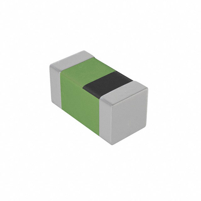
SMD PPTC (Surface Mount Polymeric Positive Temperature Coefficient) fuses are designed specifically for automated surface-mount production and are among the most widely used overcurrent protection solutions in space-constrained PCB designs.
Common SMD Package Sizes
| Package Code | Dimensions L×W (mm) | Typical Ihold Range (25°C) | Common Vmax Range |
|---|---|---|---|
| 0603 | 1.6 × 0.8 | 0.01 A – 0.5 A | 6 V – 60 V |
| 0805 | 2.0 × 1.25 | 0.05 A – 1.0 A | 6 V – 24 V |
| 1206 | 3.2 × 1.6 | 0.05 A – 2.0 A | 6 V – 60 V |
| 1210 | 3.2 × 2.5 | 0.05 A – 2.0 A | 6 V – 50 V |
| 1812 | 4.5 × 3.2 | 0.1 A – 3.0 A | 6 V – 60 V |
| 2920 | 7.0 × 5.0 | 0.3 A – 5.0 A | 12 V – 60 V |
USB Port Protection — Worked Example
- Circuit parameters: normal load current 1.5 A, max ambient 60°C, operating voltage 5 V.
- Temperature derating: apply the datasheet derating curve. Rule of thumb: Ihold (25°C) ≥ operating current ÷ 0.75. Required: 1.5 A ÷ 0.75 = 2.0 A.
- Voltage: select Vmax > 5 V (e.g., 6 V or higher).
- Package: 1812 or 2920 depending on PCB space and rated current.
- Verify trip time: confirm trip time at fault current is within the downstream component's tolerance window.
- Verify DC resistance: at 2 A with R1max = 0.03 Ω, voltage drop = 0.06 V, power dissipation = 0.12 W — acceptable.
Major SMD PPTC Brands
- Littelfuse: standard, low-resistance, and AEC-Q200 automotive-grade SMD series.
- Bourns: comprehensive SMD product line including Multifuse® series.
- YAGEO: wide package range from 0603 to 2920.
- Fuzetec: SMD including ultra-low resistance (Low Rho) series.
- JinRui (JK): leading domestic manufacturer covering wide SMD package range.
- TLC: SMD series from 0603 to 2920, widely used in consumer electronics.
- Semiware: SMD resettable fuses including 0805 package.








.png?x-oss-process=image/format,webp/resize,h_32)


