
 German
 Japanese
 Portuguese
 Korea
Korea
 Mexico
 Dutch
Dutch


What Are The Different Types Of Surge Current Limiters?

Table of Contents
Thermistor Inrush Current Limiter
Thermistor Inrush Current Limiter: At its core is a power-grade NTC (Negative Temperature Coefficient) thermistor. Leveraging the characteristic of “high resistance when cold and low resistance when hot,” it is connected in series at the circuit input to suppress high inrush currents during startup. It serves as a standard protective component for devices such as switching power supplies and inverters.

I. Core Operating Principle
NTC (Negative Temperature Coefficient) thermistors are made of metal oxide ceramics, and their resistance decreases exponentially as temperature rises.
At power-on (cold state)
The ambient temperature is low, and the NTC exhibits high resistance (e.g., 5Ω, 10Ω).
When connected in series with the power supply circuit, it effectively limits the inrush current during the charging of the filter capacitor.
Example: In a 220V circuit, the surge current can reach 311A without an NTC; after connecting a 10Ω NTC in series, the peak drops to ~28A.
Normal Operation (Hot State)
Current flowing through the NTC generates self-heating, causing the temperature to rise rapidly.
The resistance drops sharply to 0.5–2Ω (low residual resistance).
Power dissipation is extremely low, voltage drop is minimal, and the circuit operates efficiently and stably.
Power-Off Cooling
After power is disconnected, the NTC gradually cools down, returning to its cold-state high resistance within tens of seconds to several minutes, ready for the next startup.
II. Key Electrical Parameters (Core Selection Criteria)
R25 (25°C zero-power resistance): Cold-state nominal resistance value (e.g., 5D-11, 8D-20; the number preceding “D” represents the R25 value).
B-value (Material Constant): Determines the resistance-temperature sensitivity; the higher the B-value, the greater the difference between cold and hot resistance, resulting in better suppression performance.
Imax (Maximum Steady-State Current): The long-term allowable operating current for the NTC (typically 1–10 A).
Maximum Energy Rating (J): The energy it can withstand during a single power-on surge (e.g., 100 J, 200 J).
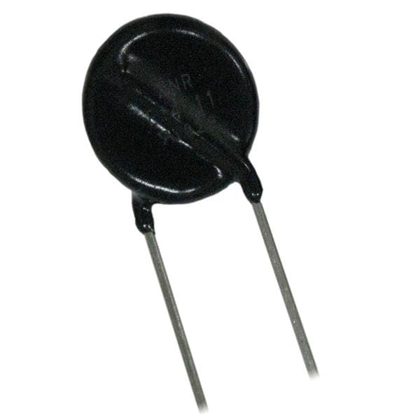
Dimensions / Package: Power-type NTCs are typically disc-shaped (5–20 mm diameter) with radial leads.
| Characteristic | NTC Thermistor | Fixed Current-Limiting Resistor |
|---|---|---|
| Start-up Current Limiting | Strong (high resistance) | Moderate (fixed resistance) |
| Steady-state Power Dissipation | Extremely low (low resistance at operating temperature) | High (voltage drop across the entire range) |
| Circuit Efficiency | High (Energy-saving) | Low (High loss) |
| Applications | High-efficiency power supplies, long-running equipment | Low-power, intermittent-duty equipment |
IV. Typical Applications
Switching power supplies (SMPS), adapters, chargers
Inverters, servo drives, UPS
LED drivers, electronic ballasts
Motor starting circuits, industrial control equipment
Audio amplifiers, medical power supplies, telecommunications power supplies
V. Limitations and Precautions
Thermal Memory Effect: During frequent power cycling (<1 minute), the NTC has not cooled down and its resistance has not recovered, resulting in the failure of surge suppression.
Steady-State Voltage Drop: A slight residual resistance remains in the hot state; for applications requiring extremely low voltage drop, a relay bypass must be used.
Heat Dissipation and Derating: High-current applications must ensure adequate heat dissipation; derating improves lifespan and reliability.
Ntc Thermistor Inrush Current Limiter

I. What Is It?
Full Name: Power-Grade NTC (Negative Temperature Coefficient) Thermistor
Function: Suppresses inrush current during power-on, protecting the rectifier bridge, capacitors, fuses, and MOSFETs from being damaged by the surge.
II. Core Principle (In a Nutshell)
High resistance when cold → Current limiting;
Very low resistance when hot → No power consumption.
Cold Start State (High Resistance)
Low temperature → High resistance; connected in series with the AC input or DC bus to limit charging current.
Operating State (Low Resistance)
Current flow generates heat → Resistance drops sharply → Extremely low power consumption and minimal voltage drop.
Power-Off Cooling
Temperature drops → Resistance returns to normal, ready for the next startup.
III. Typical Structure
Disc-shaped ceramic power NTC
Common Models: 5D-11, 8D-11, 10D-11, 16D-20, 20D-20, etc.
The number preceding “D” = Cold-state resistance at 25°C (Ω)
IV. Advantages
Extremely low cost
No mechanical movement, silent operation, reliable
Operates automatically, no control required
Strong inrush current limiting, low steady-state power loss
V. Disadvantages (Very Critical)
Thermal memory effect
If restarted immediately after shutdown → The NTC is still hot, resulting in low resistance → Loses its current-limiting function.
Minor power consumption during long-term operation; a relay bypass is required in high-current scenarios.
VI. Typical Applications
All power supplies with large-capacitor filtering:
Switching power supplies, adapters, chargers
LED drivers
Inverters, UPS systems, servo drives
Audio amplifiers, industrial power supplies
VII. Simple Selection Guidelines
High voltage, large capacitance → Choose a higher resistance value (10Ω, 16Ω)
High current → Choose a larger size with higher Imax (20D series)
Frequent power cycling → Must use NTC + relay bypass
Active Inrush Current Limiter
Core Definition: Dynamically limits inrush current using electronic switches (MOSFET/SCR) and control circuits, rather than relying on passive components such as NTCs or fixed resistors, thereby achieving both high current-limiting accuracy and low steady-state power loss.

I. Core Principles
Series-connected controlled switch: A power MOSFET or SCR is connected in series with the power supply input circuit to replace NTCs or fixed resistors.
Closed-Loop Dynamic Control: During the initial power-up phase, the control circuit maintains the switch in the linear region or allows it to turn on gradually, limiting the current peak to a preset threshold (e.g., ≤ 1.5–2 times the rated current).
Full-Conduction Low Loss: Once the input capacitance is fully charged, the switch rapidly enters the saturated conduction state, with an extremely low on-resistance (Rds(on)) in the milliohm range, resulting in steady-state losses far lower than those of an NTC.
Key Triggering Methods:
Voltage Zero-Crossing Synchronization: For AC input, the switch turns on gradually at the voltage zero-crossing point to eliminate inrush current.
Current/Voltage Threshold: The switch turns fully on once the current or voltage reaches the threshold.
Soft-Start Ramp: The gate is controlled via RC or PWM to regulate the voltage rise rate di/dt.
| Topology | Core Components | Applications | Advantages | Disadvantages |
|---|---|---|---|---|
| MOSFET Soft Start | N/P-MOSFET + Gate Driver + Sense Resistor | Small to medium power DC/AC, server power supplies | Fast response, high efficiency, integrable | Requires gate driver and protection, slightly higher cost |
| SCR Phase-Shift Control | Thyristor + Phase-Shift Trigger | Medium-to-high-power AC-DC, charging stations | High voltage rating, simple drive | Requires zero-crossing for turn-off, high control complexity |
| Dedicated Control IC | Surge suppression IC + MOSFET | Consumer electronics, industrial power supplies | Extremely simple design, high reliability | Custom |
Standard Circuit Example (MOSFET High-Side Soft Start)
A N-MOSFET is connected in series with the live wire, and a sense resistor Rs monitors the current.
During power-up, an op-amp or comparator controls the gate to keep the MOSFET in the linear region, clamping the current at Ilim = Vref/Rs.
Once the capacitor is fully charged, the gate is driven to full conduction, and Rs retains only its current-sensing function.
III. Key Advantages (Compared to NTC)
No thermal memory effect: Supports frequent and rapid power cycling; NTCs fail due to insufficient cooling.
Ultimate Efficiency: Saturation conduction loss < 0.25W, far lower than the 0.5W of an NTC (in a 15W power supply scenario).
Precise Control: Adjustable current-limiting threshold to accommodate different loads and voltage levels.
No Volume Temperature Rise: Performance remains stable over the long term, unaffected by ambient temperature changes.
High Integration: Can be integrated into power modules, reducing the number of external components.
IV. Limitations and Design Considerations
Cost and Complexity: Requires components such as MOSFETs, drivers, and sampling resistors, resulting in a higher design barrier than NTC solutions.
Component Selection:
MOSFET: Low Rds(on) and high current margin to balance efficiency and reliability.
Sampling Resistor: Low resistance and high power rating to prevent heat from affecting accuracy.
Drive Circuit: Fast response to prevent secondary breakdown of the MOSFET.
Protection Functions: Must integrate overcurrent, overtemperature, and short-circuit protection to enhance robustness.
EMI Considerations: Soft-start ramps may affect EMI; control strategies must be optimized.
V. Applicable Scenarios
High Reliability: Server power supplies, communication base stations, industrial UPS.
Frequent Start-Stop Cycles: Robots, test equipment, medical devices.
High Power / High Efficiency: Power supplies >500W, charging stations, new energy vehicle power supplies.
Precision Control: Laboratory power supplies, aerospace power supplies.
VI. Selection and Implementation Recommendations
Define Boundaries First: Clearly define the input voltage range, maximum output power, target current limit peak, and recovery time.
Preferred Solutions:
Small to medium power (<1kW): Select MOSFET soft-start solutions with high integration.
Medium to high power (1–10kW): Select SCR phase-shift or controlled bridge topologies.
Rapid Implementation: Use dedicated surge suppression ICs to reduce design costs.
Derating Design: Ensure MOSFET current margin ≥2 times and sampling resistor power rating ≥3 times to guarantee long-term reliability.
3 Phase Inrush Current Limiter
Here’s the most practical and clear guide for industrial settings, variable frequency drives, UPS systems, and high-power rectifiers—no fluff, just solutions ready for any engineering application.

I. Purpose
Limits the inrush current that charges large-capacity electrolytic capacitors downstream during three-phase AC startup, protecting:
Rectifier bridges (three-phase rectifier bridges)
Fuses, circuit breakers
Contactors, IGBTs/MOSFETs
II. Three Common Three-Phase Solutions (Industry Standard)
1. Three-Phase Passive NTC Surge Limiting (Simplest)
Connect one high-power NTC in series with each phase (3 total)
High resistance at cold state → Current limiting
Low resistance at hot state → Low loss
Advantages: Simplest, cheapest, no control required, maintenance-free
Disadvantages: Thermal memory; fails with frequent restarts
Applications: Power supplies and inverters below 30 kW with infrequent start-stop cycles.
2. Three-Phase Resistor + Contactor Bypass (Most Common in Industry)
Structure:
One current-limiting resistor in series with each phase (3 total)
After the capacitor is fully charged, the contactor (three-phase contacts) shorts the resistor
Operation:
Power-on → Current-limited charging via resistors
Delay of 1–3 seconds → Contactor engages → Resistors are short-circuited
Normal operation, zero power loss
Advantages:
No thermal memory; supports frequent restarts
Highly reliable; industrial standard
Moderate cost
Disadvantages: Mechanical contacts; audible switching noise
Applications: Variable frequency drives, UPS, PV inverters, electroplating power supplies, medium-frequency power supplies (The vast majority of high-power three-phase equipment)
3. Three-Phase Active Soft Start (Active Inrush Limiter)
Uses 3 MOSFETs / 6 SCRs for electronic soft start, featuring contactless, stepless current limiting.
Control Method:
Phase-shift voltage regulation
Gradual voltage rise
Closed-loop current limiting
Advantages:
Contactless, silent, extremely long lifespan
Precise current limiting
Supports ultra-frequent starts
No inrush current; low EMI
Disadvantages: Expensive, complex
Applications: High-end UPS, server power supplies, military, medical, high-voltage inverters
IV. Engineering Selection Guidelines
≤15kW: Three-phase NTC
15~200kW: Resistor + contactor (standard solution)
Above 200kW / High-end equipment: Active soft starter or SCR soft starter
L1 ──[Current-limiting resistor R]───┬───────────┐
L2 ──[Current-limiting resistor R]───┼──Rectifier bridge───Capacitor
L3 ──[Current-limiting resistor R]───┴───────────┘
                    │
                    └──[Three-phase contactor contacts] Parallel short-circuit resistors
Ac Inrush Current Limiter Circuit
The inrush current during startup of all AC (110/220/380V) equipment is essentially caused by the charging surge of large capacitors. Therefore, there are only four classic configurations for current-limiting circuits:

1. NTC thermistor (passive, simplest)
Circuit:
Connect one power-rated NTC in series with the live wire
AC live wire → NTC → Rectifier bridge → Capacitor
Principle:
High cold-state resistance → Current limiting
Low hot-state resistance → Low power loss
Advantages:
Simplest and cheapest
No relays, no noise
Operates automatically
Disadvantages:
Thermal memory effect: Immediate restart after shutdown → Failure
Applications: Low power, infrequent starts (power adapters, LED power supplies, small amplifiers)
II. Current-Limiting Resistor + Relay Bypass (Most Common for AC, Best Value)
AC Live Wire → Current-Limiting Resistor R → Load
        Resistor in parallel with relay contacts
Operation:
Power-on: Resistor limits current, capacitor charges slowly
Delay 0.5–2 seconds: Relay engages, short-circuits the resistor
Normal operation: Zero loss
Advantages:
No thermal memory; supports frequent restarting
Extremely reliable; industrial standard
Low cost
Disadvantages:
Mechanical contacts; slight clicking sound upon engagement
This is the standard solution for 90% of high-power AC equipment:
Inverters, UPS systems, welders, air conditioners, servo drives
III. Active Soft-Start Circuit (MOSFET, Contactless)
AC live wire → Power MOSFET → Load
        └ Drive control (gate soft-start)
Principle:
Controls the MOSFET to turn on gradually, allowing the voltage to rise slowly and limiting the current to a set value.
Once fully charged, the MOSFET turns on completely; Rds(on) is in the milliohm range, resulting in virtually no loss.
Advantages:
Contactless, silent, extremely long lifespan
Precise current limiting
Supports unlimited frequent restarts
Disadvantages:
High cost, requires control circuitry
Applications: High-end power supplies, medical, military, servers
IV. TRIAC Soft Start (AC-Specific)
Live wire → TRIAC → Load
      Phase-shift triggering control
Principle:
By controlling the conduction angle through phase-shift, the input voltage gradually rises from 0 to full voltage, achieving a smooth soft start.
Suitable for high-power AC motors, heating elements, and large capacitors.
Advantages:
Perfectly suited for AC
Contactless, high power
Smooth current limiting
Disadvantages:
Generates harmonics; slightly poorer EMI performance
Capacitor Inrush Current Limiting

I. Why Do Surges Occur?
At power-up: Capacitor voltage = 0V → This is equivalent to the peak AC voltage being applied directly across the loop impedance, resulting in an instantaneous surge in current: Irush = Rloop × Upeak
220V: Peak ≈ 311V
380V: Peak ≈ 537V
Circuit resistance is extremely low → Inrush current can reach tens to hundreds of amperes, directly blowing the rectifier bridge, fusing the fuse, and damaging the capacitor.
II. There are only 4 standard circuits for limiting capacitor inrush current
All use series current-limiting components; there are no other solutions.
1) NTC Thermistor (Simplest)
Connected in series with the capacitor charging circuit
Cold state: High resistance → Current limiting
Hot state: Low resistance → Low loss
Advantages: Simple, inexpensive, contactless Disadvantages: Thermal memory, fails during rapid restart
Applications: Low power, infrequent startup
2) Current-limiting resistor + relay / contactor bypass (Most versatile, most reliable) Power supply → Current-limiting resistor R → Capacitor
Resistor in parallel with relay contacts
Operating sequence:
Power-on → R current-limiting charging
Delay 0.5–2 seconds → Relay engages, short-circuiting R
Normal operation → Zero loss
Advantages:
No thermal memory; supports frequent restarts
Larger capacitors perform better
Industrial standard solution
90% of high-power capacitor charging uses this!
3) Active Soft Start (MOSFET Electronic Current Limiting)
Power supply → MOSFET → Capacitor
Gate soft-start control
Controls the MOSFET to turn on gradually, strictly limiting the current. Once fully charged, it turns on completely, resulting in milliohm-level losses.
Advantages: Contactless, silent, precise current limiting
Disadvantages: Expensive, complex
4) Fixed Resistor (No Bypass, Low Power Only)
Only a resistor in series, no short circuit. Advantages: Simplest. Disadvantages: Constant heat generation, high losses, low efficiency.
Used only for extremely small capacitors and extremely low power.
III. Key Formulas for DC Applications
1. Calculating the Current-Limiting Resistor
R = Irush_max × VDC
Example: 48V, 2A limit: R = 48 / 2 = 24Ω
2. Resistor Power Rating
Charging time is extremely short (tens of milliseconds); a 5W–10W cement resistor is sufficient
3. MOSFET
N-channel MOSFETs are best suited for the low-side, while P-channel MOSFETs are best suited for the high-side. The lower the on-resistance, the better (mΩ range)
Dc Inrush Current Limiter
DC Inrush Current Limiter (Specifically designed for current limiting during power-up of capacitors, busbars, and loads)
I’ll give you the most concise, engineering-focused, and practical version—covering only DC applications, without mixing in AC.

I. Why Limit Current in DC Systems?
During DC power-up: The capacitance C at the output end acts as a short circuit, causing the bus voltage to be directly applied across the wire resistance → Instantaneous inrush current can reach tens to hundreds of amperes, blowing MOSFETs, melting fuses, damaging capacitors, and overloading the power supply.
II. There Are Only 3 Classic Circuits for DC Inrush Limiting (All Universally Applicable)
1. NTC Thermistor (Simplest, Passive)
Connected in series with the DC bus: DC+ → NTC → Capacitor/Load → DC-
High resistance in cold state → Current limiting
Low resistance in hot state → Low power loss
Advantages: Simple, inexpensive, no control required Disadvantages: Thermal memory effect; fails during rapid restart
Applications: Low power, infrequent start-stop cycles
2. Current-limiting resistor + MOSFET bypass (the most standard and robust DC solution)
This is the active DC surge limiter; 90% of industrial applications use it.
Circuit structure: DC+ → R (current-limiting resistor) → Load/C
Parallel MOSFET (N-channel or P-channel)
Operating logic:
Power-on: Resistor R limits current during charging
Capacitor voltage rises → Control circuit turns on MOSFET
MOSFET fully conducts → Short-circuits R → Zero loss
Advantages:
No thermal memory; supports frequent restarting
No relays, no contacts, silent operation
Perfectly suited for DC
Low cost, extremely reliable
This is:
Active DC Inrush Current Limiter
3. MOS Linear Soft Start (Resistor-Free, Purely Active) DC+ → MOSFET → Capacitor/Load
Gate RC soft start
The gate charges slowly through the capacitor-resistor circuit
The MOSFET transitions gradually from the saturation region to the linear region and then fully conducts
Current rises smoothly, with no inrush
Advantages: No resistors, no contacts, high-end design
Disadvantages: The MOSFET must withstand linear losses, requiring a high-power MOSFET
Applications: High-end power supplies, servers, automotive, military
III. Key Formulas for DC Applications
1. Calculating the Current-Limiting Resistor
R = Irush_max × VDC
Example: 48V, 2A limit: R = 48 / 2 = 24Ω
2. Resistor Power Rating
Charging time is extremely short (tens of milliseconds); a 5W–10W cement resistor is sufficient
3. MOSFET
N-channel MOSFETs are best suited for the low-side, while P-channel MOSFETs are best suited for the high-side. The lower the on-resistance, the better (mΩ range)


.png?x-oss-process=image/format,webp/resize,h_32)


