
 German
 Japanese
 Portuguese
 Korea
Korea
 Mexico
 Dutch
Dutch


Cable Pull Switches: Complete Guide, Types, Safety Features, Installation and Selection

Cable Pull Switches
A cable pull switch, also called a cord pull switch, is a mechanical switching device that controls the on/off state of an electrical circuit by pulling a cord, cable, or wire rope. Cable pull switches are used in a wide range of applications, from traditional household pull-cord light switches to industrial emergency stop devices installed along conveyors, production lines, and large machinery.
Household Cord Pull Switches: Simple On/Off Control
In early residential electrical installations, pull-cord switches were commonly used to control lighting. Pulling an insulated cord would switch the light on or off. The basic mechanism is simple, reliable, and easy to operate.
- Ratchet mechanism: The core mechanical component. Each pull rotates the ratchet by a fixed angle, changing the switch state.
- Contact system: Usually composed of rotating copper forks and spring-loaded copper electrodes, which mechanically connect or disconnect the circuit.
- Mechanical latch: Keeps the switch firmly in the “on” or “off” position without requiring continuous pulling force.
Industrial Pull-Wire Switches: Critical Emergency Stop Devices
In industrial environments, cable pull switches are most commonly used as emergency stop devices. They are also known as pull-wire switches, rope pull switches, or emergency stop pull-wire switches. Their primary function is to immediately stop running equipment in hazardous situations, helping protect both operators and machinery.
Main Types of Cable Pull Switches
| Type | Description |
|---|---|
| Two-way pull-wire switches | The most common industrial type. Steel cables are installed on both sides of a conveyor belt, and pulling the cable at any point triggers a stop signal. These switches usually include a self-locking function and require manual reset to prevent accidental restart. |
| Explosion-proof pull cord switches | Designed with explosion-proof housings for hazardous locations containing explosive gases or dust, such as coal mines, chemical plants, and petrochemical facilities. For example, some SW-4 series switches feature ExdIIBT6 explosion-proof certification and an IP54 protection rating. |
| Single-end and double-end pull-wire switches | In a single-end design, one end of the pull wire is connected to the switch and the other end is fixed to a structural point. In a double-end design, both sides are connected to the switch, enabling more complex monitoring and control. |
| Encoded intelligent emergency stop switches | Advanced models can transmit detailed status and diagnostic signals, making them suitable for complex automation systems and intelligent production lines. |
Core Components
- Sealed housing: Usually made of metal, engineering plastic, stainless steel, or explosion-proof material. The enclosure protects the internal switch mechanism and determines the IP protection rating.
- Pull cord or wire rope: The component that directly receives tensile force and transmits the pulling action. Industrial systems often use steel wire rope with a diameter of approximately 4 mm.
- Actuator arm and reset mechanism: Transfers the pulling force to the switch mechanism and enables manual reset, usually with a spring-assisted mechanism.
- Microswitch contact system: The internal electrical switching element, commonly including normally open contacts and normally closed contacts.
- Manual reset knob or button: After the switch has been triggered and mechanically locked, it must be manually reset before the equipment can restart.
- Status indicator light: Provides a visual indication of the switch status, such as normal, triggered, or fault state.
- Cable entry or cable gland: Allows electrical cables to enter the switch while maintaining dustproof, waterproof, or explosion-proof performance. A common size is G3/4".
Operating Principle
- Pulling the cable: An operator manually pulls the wire rope installed along the equipment.
- Triggering the mechanism: The pulling force is transmitted into the switch, rotating the actuator arm and activating a cam or linkage mechanism.
- Contact operation: The mechanism actuates the microswitch, causing the normally closed contacts to open and the normally open contacts to close.
- Signal output: The contact status change sends an emergency stop signal to a PLC, safety relay, or control circuit.
- Mechanical latching: After triggering, the mechanism locks mechanically and maintains the safe stop state until manually reset.
Key Technical Parameters
The following parameters should be considered when selecting a cable pull switch:
- Cable length: Determines the effective control range. Depending on the model, the control distance may range from several meters to more than 100 meters.
- Contact rating: Indicates the voltage and current that the switch contacts can safely switch, such as AC 220 V / 4 A or AC 380 V / 5 A for some explosion-proof models.
- Number of contacts: Common configurations include 1NO/1NC, 2NC, 2NC/2NO, 3NC/1NO, and similar combinations.
- Protection rating: IP65, IP66, or IP67 ratings are recommended for outdoor, humid, or dusty environments.
- Explosion-proof rating: Indicates suitability for hazardous gas or dust environments, such as ExdIIBT6.
- Reset method: Safety circuits should use manual reset rather than automatic reset.
- Operating force: The minimum pulling force required to trigger the switch, measured in newtons.
- Operating temperature: The ambient temperature range within which the switch can operate normally.
- Reliability: Usually expressed as mechanical or electrical life, such as more than 100,000 cycles.
- Cable specifications: Explosion-proof switches often allow cable outer diameters of approximately 9 mm to 14 mm.
Key Selection Criteria
- Environmental assessment: Select the enclosure and material according to flammability, explosiveness, humidity, dust, corrosion, and washdown requirements.
- Functional requirements: Determine the required protection distance, contact configuration, reset method, alarm output, and terminal type.
- Installation requirements: Check mounting dimensions, bracket compatibility, and cable entry specifications such as G3/4".
Wiring and Cable Requirements
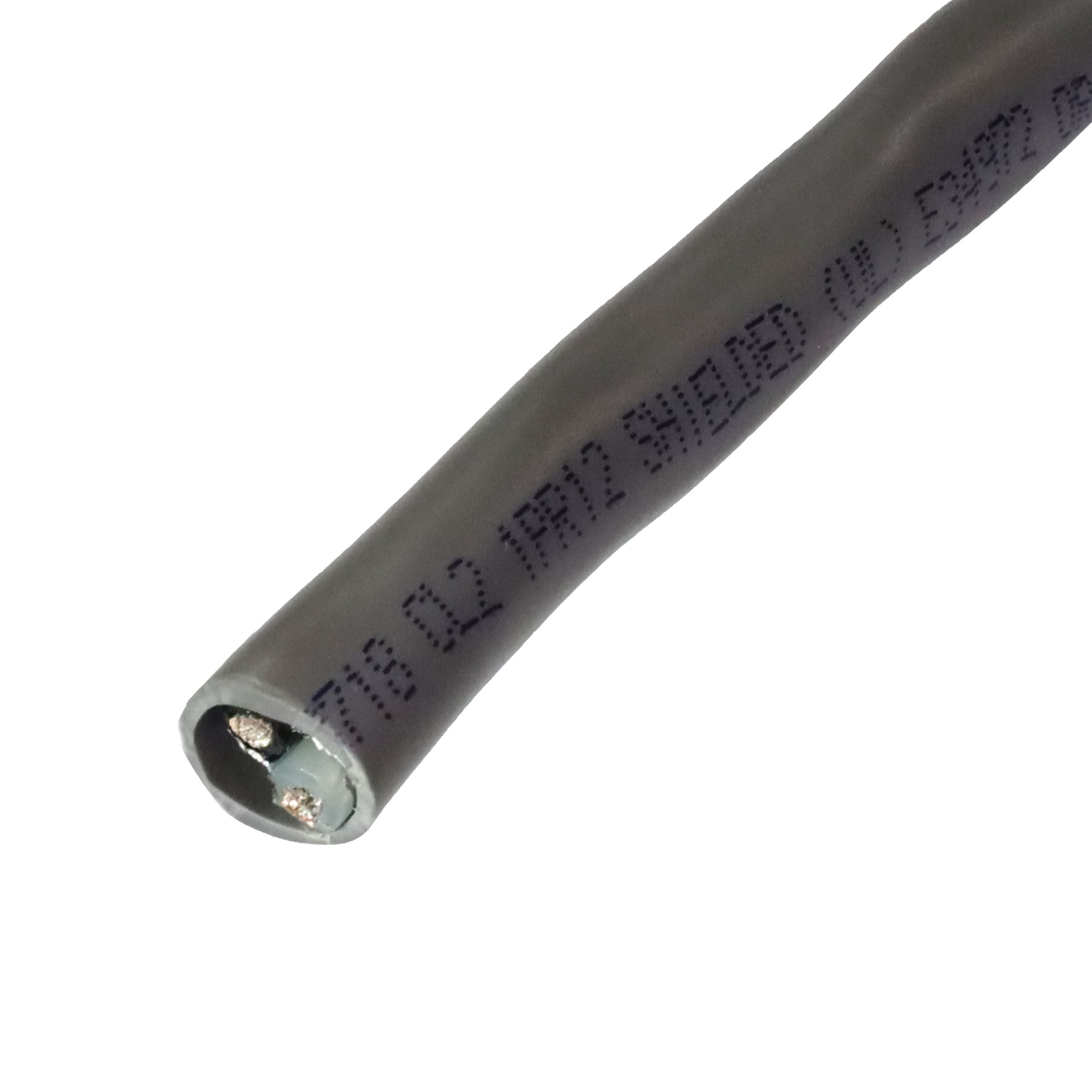
- Conductor material: Flexible, multi-strand tinned copper conductors are recommended for industrial control circuits.
- Cross-sectional area: For control circuits, 1.5–2.5 mm² wire is commonly used. For signal circuits, 1.0–1.5 mm² is typical. For long distances greater than 50 meters, a larger cross-section may be required to reduce voltage drop.
- Insulation material: PVC is suitable for standard indoor use, while XLPE or silicone rubber is preferred for outdoor, humid, oily, or high-temperature environments.
- EMI protection: Near variable frequency drives or other strong electromagnetic interference sources, copper-braided shielded cable should be used, with the shield grounded at one end.
Installation and Maintenance
Industrial pull-wire switches are commonly installed along belt conveyors. Correct installation and regular maintenance are essential for reliable safety performance.
Installation Steps
- Positioning and mounting: Install switches at appropriate positions on both sides of the conveyor. A general recommendation is to install one switch every 20–25 meters, depending on the product and site conditions.
- Tensioning the pull cables: Connect the switches with steel wire rope and adjust tension using turnbuckles. The rope should not be too loose, which may cause false alarms, or too tight, which may affect triggering.
- Electrical connection: Connect the switch leads to the control circuit. Normally closed contacts are usually connected in series to form a safety circuit, while normally open contacts may be used for alarm signals.
Maintenance Guidelines
- Visual inspection: Periodically inspect the housing for damage, corrosion, and sealing integrity.
- Status verification: Check that indicator lights or position windows function properly.
- Functional testing: Pull the cable regularly to verify that the switch triggers, locks, stops the equipment, and can be reset manually.
- Pull cord inspection: Inspect the wire rope for wear, broken strands, jamming, or excessive slack.
- Electrical testing: Check terminal tightness and measure contact resistance with a multimeter when necessary.
Industrial Pull-Wire Switch Installation Spacing Reference
| Brand / Model | Single-End Cable Length | Distance Between Switches | Mounting Bracket Spacing |
|---|---|---|---|
| Schmersal PS216 Q200 | Up to 50 meters | - | - |
| Schmersal PS216 Q210 | Up to 100 meters | - | - |
| General Industrial Reference | Recommended: no more than 30 meters | Recommended: no more than 60 meters | - |
| Schneider XY2 Series | - | Up to 15–20 meters | Recommended: one bracket every 5 meters |
| Coal Mine ZDLX Type | - | Recommended: 50–100 meters | - |
Common Faults and Troubleshooting
- Poor contact: After long-term operation, microswitch contacts may become eroded or oxidized. Measure contact resistance regularly and replace the switch core if necessary.
- Failure to reset or self-locking problems: Usually caused by mechanical jamming, dirt buildup, or spring failure. Clean, lubricate, or replace the affected components.
- Cable too loose or too tight: Incorrect cable tension can cause false triggering or failure to trigger. Readjust tension to the recommended range.
- Broken or loose wires: Long-term vibration and bending may damage wiring. Use a multimeter to check continuity and repair damaged wiring.
- Water ingress due to seal failure: Aging or damaged O-rings may lead to internal corrosion. Replace seals regularly and inspect the housing for cracks.
Cable Pull Safety Switch
A cable pull safety switch is a dedicated industrial safety device used to perform reliable emergency stops over long distances. Unlike an ordinary cord pull switch, it is designed according to specific safety standards and incorporates multiple protective mechanisms to ensure that machinery can be stopped safely and reliably in an emergency.
Compared with general pull-cord switches, the main value of a cable pull safety switch lies in its fail-safe design. It is not only a mechanical switch, but also an essential part of a complete machine safety system.
Core Safety Design: Safety First in Every Detail
- Positive opening and direct action: When triggered, the internal contacts are forcibly opened by the mechanical structure. Even if contact welding or mechanical fault occurs, the design helps ensure reliable circuit interruption.
- Redundant contact design: Safety pull-wire switches typically include two normally closed contacts to form a redundant safety circuit. If either contact fails to open correctly, the safety circuit can stop the equipment.
- Manual reset lockout: After activation, the switch can only be restored manually using a reset knob, key, or button. This prevents accidental restart before the hazard has been removed.
- Wire break and slack detection: Some advanced models automatically issue a stop signal when the wire rope breaks, becomes too loose, or loses tension because of temperature changes. Honeywell pull-wire switches, for example, provide dual-channel latching for both tension and slack conditions.
- High environmental adaptability: Enclosures typically provide IP65 or higher protection. For harsh environments, coated housings or SS316 stainless steel materials may be selected for corrosion resistance against acid, alkali, salt spray, or washdown conditions.
- Explosion-proof design: In hazardous areas such as coal mines and chemical plants, certified explosion-proof models are required. For example, some IDEM Guardian series switches are ATEX certified for gas and dust explosion-risk environments.
International Safety Standards
A qualified cable pull safety switch generally complies with one or more of the following standards:
- ISO 13850: Design principles for emergency stop functions.
- IEC/EN 60947-5-1: Requirements for low-voltage switchgear and controlgear.
- IEC/EN 60947-5-5: Particular requirements for emergency stop devices with mechanical latching functions.
- ISO 13849-1: Performance levels for safety-related parts of control systems, such as PL e.
- IEC 61508 / IEC 62061: Functional safety standards for electrical, electronic, and programmable electronic safety-related systems, such as SIL 3.
Because cable pull safety switches are used in personnel protection, it is essential to verify relevant certifications during product selection.
Leading Brands and Selection Guide
| Brand | Model Series | Maximum Pull Cord Length | Contact Configuration | Key Features and Certifications |
|---|---|---|---|---|
| Honeywell | 1CPS / 2CPS | ≤76 m / ≤152 m | 2NC/2NO or 3NC/1NO | Dual-channel latching for tension and slack; UL, CE, CSA, SIL 3 certified. |
| EUCHNER | RPS Series | Up to 100 m | 2 forced-break contacts + 2 NO | Correct rope tension indication; complies with EN ISO 13850. |
| Pilz | PSENrope | PSENrope ≤75 m / mini ≤30 m | 2NC + 2NO | Wiring compartment isolated from mechanical components; IP67 protection rating. |
| Rockwell Automation | 440E Lifeline 4 | Max. 75 m | 3NC + 1NO | Stainless steel construction options; CE, UL, and TÜV certifications. |
| Schmersal | Z/T Q700 / Q900 | - | 1NC/1NO, 2NC, 2NO options | Pure silver contacts; IP67 protection; complies with EN ISO 13850. |
| Bernstein | SRM Series | Up to 75 m | - | Unique pull-cord status indication; IP67 protection rating. |
| Schneider Electric | XY2C Series | XY2CH <15 m / XY2CE <50 m / XY2CB <100 m | 1NO/1NC, 2NC, 2NC/1NO | CE, UL, CSA certified; intuitive indicator window. |
| Go4B | Pullswitch | Up to 60 m / 200 ft installation distance | 6 independent changeover contacts | “Taut Wire” patented design; NEMA 4/4X/9 protection. |
| IDEM | Guardian Series | Up to 80–100 m with two switches | - | ATEX-certified explosion-proof versions for gas and dust environments; IP67/IP69K protection. |
| Banner Engineering | RP-LS42F-75LE | Up to 75 m | 2NC + 2NO | IP67 protection; mechanical life greater than 1 million cycles. |
Please note that the above are only representative brands and models. Many other manufacturers also provide high-quality cable pull safety switches, including SEM and other industrial safety component suppliers.
Integration into Safety Circuits
The safety function of a cable pull switch depends not only on the switch itself, but also on how it is integrated into the safety control system. The switch contacts should be connected to a safety relay or safety PLC. The safety controller continuously monitors the status of the contacts, creating a complete safety circuit.
Status Indication and Cable Requirements
- Visual status indication: Professional switches often include LED indicators or mechanical windows so operators can quickly identify whether the switch is reset, triggered, or faulty.
- Professional cable requirements: Industrial connection cables should use flexible, multi-strand tinned copper conductors. Control circuits typically use 1.5–2.5 mm² cable, while signal circuits usually use 1.0–1.5 mm² cable. Shielded cable should be used in interference-prone areas and grounded at one end.
Application Limits and Safety Philosophy
A pull-cord safety switch is normally not intended to be the sole means of personnel protection. It should be used as part of a broader machine safety strategy that may also include physical guarding, interlock switches, light curtains, safety scanners, safety relays, and safety PLCs.
Typical Application Scenarios
- Long-distance conveyor belts: Operators can pull the steel cable at any point along the conveyor to activate an emergency stop.
- Perimeters of large rotating machinery: Used where fixed guards are difficult to install, such as large presses or injection molding machines.
- Hazardous area boundaries: A pull cord may be installed at the entrance of a hazardous area to stop machinery before entry.
- Extreme environments: Mining, chemical processing, and food processing may require explosion-proof, stainless steel, corrosion-resistant, or high-pressure washdown models.
Operation and Maintenance Points
- Functional testing: A pull test should be conducted weekly to ensure the switch triggers, locks, stops the equipment, and resets manually.
- Tension adjustment: Check the wire rope tension monthly and adjust it to avoid false trips caused by slack or excessive tension.
- Visual inspection and lubrication: Inspect the housing for damage and corrosion. Clean and lubricate moving parts when required.
- Electrical inspection: Check terminals quarterly and verify contact continuity.
- Annual maintenance: Perform a full inspection, replace aged wire rope, clean internal dust where applicable, and test insulation resistance.
Cable Pull Emergency Stop Switch
A cable pull emergency stop switch is an emergency shutdown device designed for machinery that covers long distances or large areas. It uses a mechanically latched pull-cord mechanism to extend the emergency stop command from a single point to an entire line. Operators can immediately stop the machine by pulling the wire rope at any point along the protected area.
Core Functions and Advantages
Compared with traditional push-button emergency stops, the main advantage of a cable pull emergency stop switch is its wide coverage. By installing a steel cable along a conveyor line or around the perimeter of equipment, an emergency stop can be initiated from virtually any point along the route. This makes it ideal for applications where operators move along the machine or where guardrails cannot be installed.
A reliable cable pull emergency stop switch normally includes the following safety features:
- Positive opening: Even if contacts stick, the internal mechanical structure forces them apart to ensure safe disconnection.
- Contact redundancy and self-locking: At least two normally closed safety contacts are often used to form a redundant safety circuit. After activation, the mechanism self-locks and requires manual reset.
- Fail-safe function: Wire rope breakage or excessive slack can also trigger a shutdown, preventing loss of safety function.
- High environmental adaptability: IP67 or similar protection ratings are common. Explosion-proof versions are available for hazardous environments.
Key Safety Standards
- ISO 13850 / EN ISO 13850: Defines the design principles for emergency stop functions.
- IEC/EN 60947-5-5: Specifies requirements for emergency stop devices, including pull-wire switches and emergency stop buttons.
- ISO 13849-1 / EN ISO 13849-1 and IEC 62061: Define Performance Level and Safety Integrity Level requirements for safety-related control systems. High-risk applications may require PL e or SIL 3.
Together, these standards help ensure the reliability and safety performance of the emergency stop system.
How to Integrate It into a Safety System
A cable pull emergency stop switch is typically integrated into the equipment’s overall safety circuit as part of the emergency stop function.
- Safety circuit connection: The normally closed safety contacts should be connected to a safety relay or safety PLC in a dual-channel safety circuit. Physical disconnection of either channel should trigger a shutdown.
- Reliable wiring: Multi-strand tinned copper-core shielded cable is recommended to improve signal stability and resistance to interference.
Allen Bradley Cable Pull Switch
Allen-Bradley, a Rockwell Automation brand, offers industrial cable pull safety switches under the Guardmaster® Lifeline™ series. These products are widely used in conveyor systems, production lines, packaging machinery, material handling systems, food and beverage processing, and other industrial safety applications.
Allen-Bradley cable pull switches are mainly identified by model numbers beginning with 440E. The commonly used product families include Lifeline 3, Lifeline 4, and Lifeline 5. Each series is designed for different cable span lengths, safety requirements, environmental conditions, and diagnostic needs.
Allen-Bradley Lifeline Series Comparison
| Features / Specifications | Lifeline 3 | Lifeline 4 | Lifeline 5 |
|---|---|---|---|
| Technology Type | Electromechanical | Electromechanical | Microprocessor-based solid-state electronic technology |
| Maximum Cable Length | Up to 30 meters / 98 feet | Standard version: up to 75 meters / 246 feet Stainless steel version: up to 125 meters / 410 feet |
Up to 100 meters / 328 feet |
| Housing Material | Yellow die-cast alloy | Die-cast alloy; optional 316 stainless steel | Die-cast aluminum or 316 stainless steel |
| Protection Rating | IP67 | Stainless steel version: IP66 / IP67 | Aluminum version: IP66 Stainless steel version: IP69K, suitable for high-temperature and high-pressure washdown environments |
| Contact / Output Configuration | 3 NC / 1 NO, such as 440E-D13112 2 NC / 2 NO, such as 440E-D13120 |
3 NC / 1 NO, such as 440E-L13135 4 NC, such as 440E-L13139 |
Microprocessor-based solid-state outputs, configurable OSSD outputs |
| Safety Rating Data | To be confirmed according to model and system architecture; typically used in Category 3 / Category 4 and PL e applications when properly integrated | B10d greater than 2 × 10⁶ operations PFHD less than 3 × 10⁻⁸ Suitable for Category 3 / Category 4, PL e, and SIL CL 3 systems |
To be confirmed according to model and application. Solid-state technology helps support higher SIL and PL safety architectures |
| Key Features | Basic electromechanical design, rugged construction, cable status indicator | Integrated emergency stop button on the switch cover, cable status indicator, and longer span options | Built-in microprocessor, electronic cable monitoring, compensation for thermal expansion and contraction, fewer false trips, LED status indication, and diagnostic functions |
| Typical Applications | Standard applications with cable spans below 30 meters | Longer protection spans and applications with hygiene or corrosion requirements. Stainless steel versions are especially suitable for the food and beverage industry | Critical applications requiring production stability, advanced diagnostics, and compensation for temperature variation |
The above data is summarized from publicly available product information. For final model selection, always refer to the latest official Rockwell Automation technical documentation, installation instructions, and safety manuals.
System Reliability and Integration
The strength of Allen-Bradley cable pull switches is not limited to the switch body itself. Their major advantage is seamless integration into the Rockwell Automation safety ecosystem, including Guardmaster safety relays, safety I/O modules, safety PLCs, and EtherNet/IP-based diagnostic systems.
- High safety levels: Lifeline 4 and Lifeline 5 products can be used in high-performance safety systems when properly selected and integrated.
- SIL CL 3: Supports Safety Integrity Level 3 applications according to IEC 62061 when used in a suitable safety architecture.
- PL e: Can support Performance Level e according to ISO 13849-1 when correctly integrated.
- Category 4: Can be used in Category 4 safety system architectures according to ISO 13849-1.
- GuardLink integration: As part of Rockwell’s GuardLink technology, diagnostic information and fault location data can be transmitted in real time via EtherNet/IP, helping reduce troubleshooting time and machine downtime.
- LED status indicators: Standard or optional LED indicators provide clear visual feedback for commissioning, operation, and maintenance.
Installation and Maintenance
Installation and maintenance should focus on the reliability of the complete safety circuit, not only the mechanical switch. Correct rope tension, proper support spacing, accurate alignment, and reliable electrical wiring are all critical.
Mechanical Installation
Follow official installation guidelines from Rockwell Automation. For long-distance applications, such as a 125-meter span using Lifeline 4 stainless steel models, it is strongly recommended to use the Lifeline Rope Tensioning System, also known as LRTS. Installation kits such as the 440E-A13xxx series can help maintain stable rope tension, simplify installation, and reduce false triggering.
Electrical Wiring
- Redundancy principle: Safety contacts, especially normally closed contacts, should be wired into a dual-channel safety circuit and monitored by a forced-guided safety relay, such as Rockwell MSR safety relays, or by safety I/O modules.
- Load matching: Ensure that the contact rating matches the voltage and current of the circuit, typically 24 V DC in modern control systems. Proper short-circuit protection should be provided.
- Lifeline 5 connection: Lifeline 5 models with solid-state OSSD outputs can be connected directly to a safety PLC or compatible safety relay, providing more flexibility than traditional electromechanical contact wiring.
Partial Reference Model List
| Model | Series | Maximum Span | Contact / Output Configuration | Housing | Protection Rating |
|---|---|---|---|---|---|
| 440E-D13112 | Lifeline 3 | 30 m | 3 NC + 1 NO | Die-cast alloy | IP67 |
| 440E-D13120 | Lifeline 3 | 30 m | 2 NC + 2 NO | Die-cast alloy | IP67 |
| 440E-L13135 | Lifeline 4 | 75 m | 3 NC + 1 NO, with emergency stop button | Die-cast alloy | To be confirmed by latest datasheet |
| 440E-L13139 | Lifeline 4 | 75 m | 4 NC, with emergency stop button | Die-cast alloy | To be confirmed by latest datasheet |
| 440E-L13042 | Lifeline 4 | 75 m | With emergency stop button; contact configuration to be confirmed | Die-cast alloy | IP66 / IP67 |
| 440E-LL5SN5 | Lifeline 5 | 100 m | No emergency stop button, 2 OSSD outputs, 5-pin M12 connector | Die-cast aluminum | IP66 |
| 440E-LL5SS8 | Lifeline 5 | 100 m | No emergency stop button, 2 OSSD inputs, 8-pin M12 connector | 316 stainless steel | IP69K |
| 440E-LL5SE8 | Lifeline 5 | 100 m | With emergency stop button, 2 OSSD inputs, 8-pin M12 connector | Die-cast aluminum | IP66 |
| 440E-L13153 | Lifeline 4 | 125 m | 2 NC + 2 NO | 316 stainless steel | IP66 |
| 440A-A17125 | Accessory | Not applicable | Indicator light, M20 conduit | Not applicable | Not applicable |
For accurate selection, visit Rockwell Automation’s official website and check the Literature Library to download the latest technical datasheets, installation instructions, and safety application guides. Accessories such as indicator lights, rope tensioning systems, brackets, and installation kits should be selected according to the switch model and application environment.
Cable Pull Limit Switch
The term cable pull limit switch is more of a functional description than a single standardized product category. In practice, it may refer to two different types of industrial devices: a cable pull safety switch used for emergency stop protection, or a limit switch used for position or travel detection.
The key difference is the design purpose. A cable pull safety switch focuses on personnel safety and emergency stop protection, while a cable pull or lever-type limit switch focuses on machine position detection and process control.
Cable Pull Safety Switch vs. Cable Pull Limit Switch
| Key Comparison Point | Cable Pull Safety Switch / Emergency Stop | Cable Pull Limit Switch / Position Detection |
|---|---|---|
| Core Function | Emergency stop and safety protection | Position, travel, or process detection |
| Purpose | Stops equipment immediately when the cable is pulled by an operator | Controls stopping, reversing, indexing, or travel limits when a moving part reaches a defined position |
| Triggering Method | The wire rope can be pulled at any point along its full length | Usually triggered when a moving machine part contacts a lever, roller, arm, or actuator |
| Safety Level | Very high. Designed with positive opening contacts and compliant with safety standards such as ISO 13850 | General industrial control component without dedicated emergency-stop safety design |
| Reset Method | Manual reset required after activation | Usually automatic reset after the external force is removed |
| Common Models | Honeywell CPS / 1CPS, Schmersal ZS71, Pilz PSENrope, Allen-Bradley Lifeline, and similar safety models | SUNS SND / SND2170, TQ441, TZ-3108, and other general-purpose limit switches |
Role 1: Cable Pull Limit Switch as an Emergency Stop Device
In many industrial contexts, the phrase “cable pull limit switch” is often used informally to describe a cable pull emergency stop switch. This type of device is designed for long-distance safety protection and is commonly installed along conveyors, bucket elevators, assembly lines, and large processing machinery.
Key Features
- Long-distance protection: Cable lengths can range from several meters to more than 100 meters, depending on the model.
- Full-line triggering: The switch can be triggered by pulling the cable at any point along its length, helping eliminate dead zones.
- Positive opening: A safety mechanism forces the normally closed contacts to open even if they stick.
- Status lockout: After activation, the switch mechanically locks and must be reset manually before operation can resume.
Typical Applications and Models
- Conveyor systems: Widely used in belt conveyors and bucket elevators in coal, power, cement, ports, mining, and logistics industries.
- Machinery perimeter protection: Used around large, multi-station, or long-distance processing equipment to provide full-line emergency stop coverage.
- Honeywell 1CPS Series: Suitable for applications up to approximately 76 meters.
- Schmersal ZS71 Series: Suitable for applications up to approximately 20 meters.
- Pilz PSENrope Series: Suitable for applications up to approximately 75 meters.
- KIEPE PRS001 / HEN002: Suitable for long-distance industrial applications.
- Fischer BX5800B Series: Suitable for applications up to approximately 125 meters.
- Snap-action bidirectional pull cord switch: Suitable for approximately 25–30 meters, with support pulleys recommended every 3 meters.
Role 2: Pull Cord Mechanisms Used as Limit Switches
Some non-safety switches may use cable, lever, or roller mechanisms to detect position. These devices function as limit switches but are not normally called safety cable pull switches. They are used for process control rather than emergency stop protection.
- Microswitches with lever or roller actuators: Compact switches used to detect mechanical position.
- General-purpose limit switches with levers: Used to control travel, stopping points, reversing actions, or machine indexing.
Quick Selection Guide
To select the correct cable pull limit switch, first define whether the application requires emergency stop protection or position detection.
- Identify the main requirement:
- If the goal is emergency stop or personnel protection, choose a cable pull safety switch.
- If the goal is position detection or travel control, choose a general limit switch or microswitch.
- Measure key parameters: Determine switch spacing, total cable length, and installation route.
- Check operating environment: Consider IP rating, ambient temperature, corrosion, washdown, dust, vibration, and explosion-proof requirements.
- Determine core functions: Select the required number of safety contacts, reset method, tension monitoring, status indication, and wiring interface.
Cable Pull Switch Accessories
A complete cable pull switch system includes far more than the switch itself. It normally consists of wire rope, mounting brackets, clamps, tensioners, support rings, pulleys, springs, cable glands, and optional signaling accessories. These accessories directly affect system reliability, safety performance, service life, and ease of maintenance.
Standard Components for a Cable Pull Switch System
| Component Category | Primary Function | Key Parameters / Specifications |
|---|---|---|
| Mounting brackets and fasteners | Securely mount the switch to a conveyor frame, machine frame, or other structure | Metal brackets; commonly fixed with M5 or M10 bolts depending on switch size and installation design |
| Steel cable / wire rope | Core operating medium that transmits pulling force and enables full-line triggering | Plastic-coated or stainless steel wire rope, commonly with a diameter of Φ4–6 mm; high tensile strength and corrosion resistance are preferred |
| Clamps / U-clips | Secure wire rope ends and joints to prevent loosening | Common types include 6KTH clamps or U-clamps; 304 stainless steel is often used in corrosion-prone environments |
| Tensioner / turnbuckle | Adjusts overall wire rope tension, compensates for slack, and helps ensure reliable actuation | Dedicated rope tensioners or standard turnbuckles may be used depending on system requirements |
| Support loop / pulley | Supports the wire rope, reduces sagging, and helps prevent accidental triggering | Often installed every 3 meters; available in metal or engineering plastic |
| Extension spring | Absorbs small tension fluctuations and helps maintain stable rope tension | Spring force and travel should match the switch’s actuation requirements |
| Cable and cable gland | Route electrical cables into the switch enclosure while maintaining sealing performance | Explosion-proof switches must use certified explosion-proof cable glands; waterproof and dustproof glands are required for outdoor or harsh environments |
Advanced Options for Higher Performance
- Allen-Bradley integrated kits: Rockwell’s Lifeline Rope Tensioning System packages wire rope, tensioner, and clamps into a single kit. Some kits are designed to reduce installation time significantly, with options available in lengths such as 10, 20, and 30 meters.
- IDEM and generic installation kits: Similar integrated kits are available for IDEM Guardian series and other industrial pull-wire switch systems.
- Mounting brackets: Standard brackets are widely used, but custom brackets may be required for non-standard conveyor frames or special machinery.
- Corrosion-resistant and explosion-proof upgrades: Stainless steel wire ropes, stainless steel support rings, coated accessories, and explosion-proof cable glands should be selected for corrosive or hazardous environments.
- On-site alarm lights: Visual or audible-visual alarm devices can indicate switch activation and help personnel locate faults quickly.
- LED indicators: High-performance switches may support LED status indication for easier troubleshooting.
- Address encoders: Addressable systems can identify the exact location of the triggered switch, which is useful for large conveyor lines and long-distance material handling systems.
Installation and Maintenance Tips
- Standard switch spacing: On straight conveyor sections, switch spacing is commonly 30–50 meters, depending on the model and safety requirements.
- Inclined sections: Spacing should be reduced where the conveyor is inclined or where rope routing is more complex.
- Support spacing: Install a support ring or pulley approximately every 3 meters along the wire rope.
- Tension setting: The wire rope tension should be adjusted so that a lateral pull of approximately 15–25 centimeters can trigger the switch reliably, if this matches the manufacturer’s instructions.
- Routine functional testing: Perform regular pull tests, such as weekly tests, to confirm the switch triggers and resets properly.
- Visual inspection: Check wire rope wear, broken strands, loose clamps, corroded fasteners, and damaged support rings.
- Cleaning and lubrication: Remove dust and debris from support rings, pulleys, and tensioners. Apply suitable grease where required to prevent rust and mechanical jamming.
Rees Cable Pull Switch
Rees, formerly known as Mackworth G. Rees Company, was founded in 1929 and is a long-established brand in the field of electromechanical industrial control components. Rees cable pull switches are known for rugged construction, reliability, straightforward wiring, and long service life.
Rees products are widely used on industrial production lines, including automotive manufacturing, machine tools, conveyors, assembly lines, and other equipment requiring reliable emergency shutdown or remote stop functions.
Compared with modern automation brands such as Allen-Bradley, Rees cable pull switches are more traditional electromechanical devices. They are suitable for applications that require durable industrial control components but do not necessarily need advanced communication, network diagnostics, or smart monitoring functions.
Key Technical Features
- Positive-break safety contacts: The core contacts use a positive-break structure. Even if contacts become stuck, the mechanical action helps force them apart, which is an important requirement for reliable safety shutdown.
- Anti-false-trip design: The mechanical design helps minimize false trips caused by cable thermal expansion, temperature variation, or minor vibration.
- Manual lockout and reset: Once triggered, the switch locks automatically and must be reset manually by pressing the reset button. This helps prevent accidental restart before the hazard is removed.
- Rugged and durable housing: Many models use die-cast aluminum enclosures with yellow powder coating. Typical protection ratings include NEMA 12 / 13 and IP65, making them suitable for demanding industrial environments.
- Easy installation and maintenance: Positioning can be adjusted without opening the cover. The pull cord direction can be changed on site, and three 1/2-inch NPT conduit ports are commonly provided.
- Typical applications: Rees pull-wire switches are commonly used for emergency shutdown and long-distance protection on conveyors, assembly lines, and machine tools.
Main Product Series and Models
Rees pull-wire switches are mainly distinguished by model number and operating style. The following table summarizes common product categories, functions, contact configurations, and representative models.
| Product Category | Core Technology and Features | Contact Configuration | Reset Method | Typical Models |
|---|---|---|---|---|
| Tensioned wire rope type Main product line |
Positive-break contact operation, illuminated red LED indicator, cable-break detection, A600 / N300 heavy-duty rating | 2 NO + 2 NC | Manual reset with blue button | 04962 Series, such as 04962-112, 04962-212, 04962-202 |
| Slack wire rope type | Force-triggered design with simpler structure. The switch body and pull cord may need to be purchased separately | Momentary 1 NO + 1 NC | Automatic / momentary reset | 03275-000 heavy-duty type |
| Non-emergency control type | Slow-make / slow-break contact operation. Not suitable for emergency shutdown safety circuits | Examples include SPST-NC | Momentary | 04958 Series, such as 04958-150 |
Special Rees Cable Pull Switch Models
- Explosion-proof models: Suitable for environments requiring explosion-proof protection. These models use rugged explosion-proof enclosures and are generally much more expensive than standard versions.
- 04967-112: Explosion-proof, right-handed model.
- 04967-202: Explosion-proof model with indicator, left-handed configuration.
- 04953-121: Left-mounted indicator flag, 1 NC / 1 NO contacts, suitable for emergency stop or general control depending on the application.
- 04945-100: 2 NO contacts with manual reset.
Installation and Accessories Quick Reference
- Enclosure: Some models, such as 03275-000, may not include an enclosure. A separate enclosure, such as Rees model 02765-000, may be required.
- Fasteners: Certain models, including 03275-000, may include sealing gaskets and mounting screws.
- Cable / rope: Aircraft-grade steel cable is typically required. Cable specification should be selected according to actual length, load, environment, and switch requirements.
Key Installation Parameters
| Component / Parameter | Taut Cable Type | Slack Cable Type |
|---|---|---|
| Maximum Recommended Cable Length | 200 feet / approximately 61 meters | 33 feet / approximately 10 meters |
| Maximum Support Spacing | 10 feet / approximately 3 meters | 10 feet / approximately 3 meters |
| Actuation Force | Approximately 15 lbs | Approximately 0.7 lbs at 10-foot support spacing |
| Mechanical Life | Approximately 250,000 cycles | More than 1,000,000 cycles |
Installation tip: During initial installation, adjust the cable tension so that the shaft end aligns properly with the indicator hub end. Always follow the official Rees installation instructions for the selected model.
Price Reference
Rees product prices vary depending on the model, contact configuration, housing type, explosion-proof requirements, accessories, and purchasing channel. The following prices are for general reference only:
- 04958-175 non-emergency control model: Approximately USD 250.00.
- 03275-000 slack wire rope type: Approximately NT 10,000, equivalent to about RMB 2,300.
- 04944-000 tensioned wire rope type: Approximately NT 19,359, equivalent to about RMB 4,400.
- 04967-112 explosion-proof type: Higher-priced model, with a reference unit price exceeding USD 3,000.00.
For accurate pricing and lead time, consult an authorized Rees distributor or industrial automation supplier.
Telemecanique Cable Pull Switch
Telemecanique cable pull switches, now commonly associated with Schneider Electric and Telemecanique Sensors product families, are widely used for conveyor safety, long-distance emergency stop protection, and industrial machine guarding. In many applications, users may also refer to them as remote cable pull switches, wireless pull-cord switches, or pull-wire emergency stop switches, depending on the specific control method.
A remote or wireless pull-cord switch is triggered by pulling a cord or cable and then transmitting a signal to stop or control equipment. In industrial safety applications, this concept usually refers to a wireless pull-cord emergency stop system or a remote emergency stop assistance device.
This type of solution combines the long-distance coverage advantage of traditional cable pull switches with the flexible installation benefits of wireless technology. Compared with conventional wired pull-cord switches, wireless systems can reduce cabling work, simplify retrofits, and provide more flexible deployment in complex industrial environments.
Key Advantages
- No extensive wiring required: Wireless pull-cord systems reduce or eliminate the need for long cable runs, cable trays, conduit, trenching, and complex installation work. This is especially useful in areas where wiring is difficult, expensive, or impractical.
- Smarter system monitoring: Through gateways, receivers, or cloud-connected systems, wireless pull-cord switches can support remote status monitoring, real-time diagnostics, battery level reporting, signal strength display, switch status reporting, IoT connectivity, and data analysis.
- Improved system reliability: Industrial wireless technologies are designed with strong anti-interference capabilities. They can reduce failures related to cable aging, cable breakage, damaged conduits, or harsh installation routes.
- Greater installation flexibility: Wireless solutions make it easier to retrofit existing production lines, add new emergency stop points, or install safety devices on mobile equipment such as AGVs and AMRs. Equipment layout changes are also easier because the system is less restricted by cable routing.
- Remote-assisted operation: Some systems, such as IDEC emergency stop assistance systems, allow operators to trigger a remote emergency stop or call for assistance from near the machine or from a portable device.
- Lower total project cost in retrofits: In renovation projects, savings on cables, cable trays, conduits, labor, shutdown time, and commissioning can be significant.
Core Wireless Technologies
Wireless pull-cord switches and remote emergency stop systems may use different communication technologies depending on the manufacturer, safety requirements, communication distance, and interference environment.
- Standard frequency-hopping technology: Provides high reliability and strong interference resistance, making it suitable for many industrial environments.
- Low Power Wide Area Network, or LoRa: Known for long communication range and low power consumption. It is suitable for wide-area sensor networks and applications where devices operate intermittently.
- sWave.NET / Sure Cross architectures: Industrial wireless architectures designed for stable transmission in complex electromagnetic environments.
- Bluetooth Low Energy, or BLE: Used for short-range communication and portable devices. BLE is characterized by low power consumption and convenient connection to handheld equipment.
- Battery-free or self-powered technology: Some systems harvest kinetic energy, solar energy, or other energy sources. For example, Schneider Harmony XB5R wireless pushbutton technology includes battery-free wireless control concepts.
- Smart networking and management: Advanced systems may support device grouping, adjustable signal strength, multi-network deployment, address management, and remote diagnostics.
- Long battery life: Some industrial wireless switches can operate for many years, and certain models may provide battery life of up to approximately 10 years under appropriate operating conditions.
System Composition and Selection
Wireless or remote cable pull switch systems are usually not standalone components. They are typically built as complete systems consisting of transmitters, receivers, gateways, and configuration tools.
- Transmitter unit: The switch body or pull-cord device that sends a wireless signal when triggered.
- Receiver or gateway unit: Receives signals from the transmitter and converts them into conventional control signals, such as relay contacts, dry contacts, safety outputs, or communication data for PLCs and safety controllers.
- Configuration and management software: Used for pairing devices, configuring groups, monitoring status, checking signal strength, reading battery levels, and diagnosing faults.
When selecting a remote or wireless pull-cord switch, the first priority is to verify safety certification and radio compliance. Depending on the market, certifications may include CE, RoHS, FCC, UL, or other regional approvals. Both wireless performance and safety performance should be reviewed carefully, including communication distance, frequency band, data rate, reliability, Safety Integrity Level, Performance Level, power supply, battery life, environmental protection rating, and compatibility with existing control systems.
Reference Guide for Mainstream Wireless and Remote Pull-Cord Solutions
| Brand | Model Series | Key Technologies / Protocols | Maximum Pull Cord Length / Range | Key Features and Certifications |
|---|---|---|---|---|
| steute | RF 96 WH/90°-NET | sWave.NET®, lithium battery | Up to 130 meters | IP67, rugged construction, battery life of approximately 10 years under suitable conditions |
| Schneider Electric | ZBRP1 / Harmony XB5R | Wireless and battery-free kinetic energy harvesting | Approximately 60 meters, depending on environment and receiver configuration | IP66, battery-free operation, receiver sold separately |
| IDEC | XW Series / Emergency Stop Assist System | Bluetooth Low Energy, button battery | Not applicable to fixed rope length; portable use | Portable remote emergency stop assistance, battery life of approximately 10 days depending on usage |
| KJT | KJT-LS Series | LoRa private network protocol, 470–510 MHz FHSS | Typical switch spacing of 55–60 meters; communication range up to approximately 1 km depending on environment | IP65 / IP67 options, gateway support, suitable for long-distance monitoring applications |
| Banner Engineering | Sure Cross® Wireless Series | Sure Cross architecture, 2.4 GHz or 900 MHz options depending on region | Maximum span up to approximately 100 meters depending on product and site conditions | IP65 / IP67 options, wireless buttons and pendants, two-way communication support |
| Generic industrial models | DLH-ZX-LS-1F, ZNJT-KG-220-11, XER1022, S135.T2/1, TQ-441, HLSD-101C-NS | Various proprietary protocols | Typical range from 20 to 125 meters, depending on model | Feature sets and prices vary widely; detailed datasheet review is recommended before selection |
Generic models are provided only as examples. For safety-related applications, always verify product certification, safety rating, test reports, environmental performance, and compatibility with the safety controller before use.
Selection Summary for Wireless Pull-Wire Switches
- Prioritize core safety: Use the system’s Safety Integrity Level or Performance Level certification as the first screening criterion.
- Evaluate wireless performance: Test signal penetration, coverage range, and resistance to interference according to the actual site conditions, including metal structures, VFDs, motors, moving equipment, and obstacles.
- Review power supply options: Confirm battery type, battery life, replacement method, self-powered technology, charging method, and maintenance requirements.
- Ensure seamless system integration: Verify that the wireless receiver or gateway can be reliably integrated into the machine safety loop through safety relays, safety PLCs, or safety I/O modules.
- Verify environmental and regulatory compliance: Check the operating temperature range, IP rating, corrosion resistance, explosion-proof requirements, radio spectrum approval, and product safety certification for the target market.
Safety Cable Pull Switch
A safety cable pull switch is a machine safety device designed to stop equipment quickly when an operator pulls a cable, cord, or wire rope. It is commonly installed along conveyors, assembly lines, processing equipment, packaging machines, and other industrial systems where operators may need to activate an emergency stop from multiple points along a long operating area.
In practical use, the term safety cable pull switch may include conventional wired emergency stop rope switches, intelligent pull-wire switches, addressable systems, explosion-proof cable pull switches, and remote or wireless pull-cord safety solutions. The best choice depends on the machine risk level, protection distance, environment, wiring requirements, certification needs, and required diagnostic functions.
Main Safety Functions
- Emergency stop over a long distance: Operators can pull the cable from almost any point along the protected section to stop the machine.
- Manual reset: After the switch is activated, it locks mechanically and must be reset manually. This prevents automatic restart before the danger has been checked.
- Positive opening contacts: Safety contacts are mechanically forced open to help ensure reliable disconnection.
- Redundant safety channels: Many models include two normally closed contacts or multiple safety channels for integration with safety relays or safety PLCs.
- Wire break and slack monitoring: Advanced models can detect broken cables, excessive slack, or incorrect cable tension.
- Status indication: LED lights, mechanical indicators, or status windows help operators identify whether the switch is normal, triggered, or faulty.
- Environmental protection: IP65, IP66, IP67, IP69K, stainless steel, coated housing, and explosion-proof options are available for harsh environments.
Wired, Wireless, and Intelligent Safety Cable Pull Switches
Traditional wired cable pull switches remain the most common solution because they provide direct, reliable, and easy-to-monitor safety contacts. However, wireless and intelligent systems are increasingly used in applications where cable installation is difficult or where real-time diagnostic information is valuable.
| Type | Best For | Advantages | Key Considerations |
|---|---|---|---|
| Wired safety cable pull switch | Conveyors, machinery lines, standard safety circuits | Stable, direct contact output, easy safety relay integration | Requires cable wiring, conduit, and regular mechanical rope tension checks |
| Wireless safety cable pull switch | Retrofits, mobile equipment, difficult wiring areas | Flexible deployment, reduced wiring cost, remote diagnostics possible | Must verify safety certification, wireless reliability, battery life, and radio compliance |
| Intelligent or addressable pull-wire switch | Large conveyor networks and complex automation systems | Can identify fault location, provide diagnostics, and reduce troubleshooting time | Requires compatible PLC, safety controller, communication protocol, or gateway |
| Explosion-proof safety pull switch | Mining, chemical plants, grain handling, hazardous areas | Suitable for gas or dust explosion-risk environments when certified | Must match the required Ex rating, zone classification, gland type, and installation standard |
Reference Guide for Safety Cable Pull Switch Selection
The following table summarizes common brands and product concepts used for wired, wireless, and remote safety cable pull switch applications. The data is intended as a selection reference only and should always be confirmed with the latest manufacturer datasheets.
| Brand | Model Series | Key Technologies / Protocols | Maximum Pull Cord Length | Key Features and Certifications |
|---|---|---|---|---|
| steute | RF 96 WH/90°-NET | sWave.NET®, lithium battery | Up to 130 meters | IP67, rugged design, battery life of approximately 10 years |
| Schneider Electric | ZBRP1 / Harmony XB5R | Wireless, battery-free, kinetic energy harvesting | Approximately 60 meters, depending on installation conditions | IP66, battery-free transmitter, receiver sold separately |
| IDEC | XW Series / Emergency Stop Assist System | Bluetooth Low Energy, button battery | Not applicable for fixed cable span; portable system | Portable remote emergency stop assistance, battery life of approximately 10 days |
| KJT | KJT-LS Series | LoRa private network protocol, 470–510 MHz FHSS | 55–60 meters typical switch spacing | IP65 / IP67, maximum communication range up to approximately 1 km, gateway support |
| Banner Engineering | Sure Cross® Wireless Series | Sure Cross architecture, 2.4 GHz or 900 MHz depending on region | Maximum span up to approximately 100 meters | IP65 / IP67, wireless buttons and pendants, two-way communication |
| Generic industrial models | DLH-ZX-LS-1F, ZNJT-KG-220-11, XER1022, S135.T2/1, TQ-441, HLSD-101C-NS | Various proprietary protocols | Various, typically 20–125 meters | Features and pricing vary. Specific parameters and certifications must be verified before use |
Final Selection Principles
- Prioritize safety certification: The system’s SIL, PL, Category, CE, UL, TÜV, ATEX, or other certifications should be checked before considering price or convenience.
- Match the protection distance: Confirm the required cable span and choose a model that supports the total length with adequate tension stability.
- Check the installation environment: Outdoor use, dust, moisture, salt spray, oil, chemicals, high-pressure washdown, vibration, and temperature changes all affect model selection.
- Confirm contact configuration: Common safety circuit configurations include 2 NC, 2 NC + 2 NO, 3 NC + 1 NO, or solid-state OSSD outputs.
- Use proper accessories: Wire rope, supports, pulleys, springs, clamps, brackets, tensioners, glands, and indicator lights should be selected as part of the complete system.
- Integrate with a safety controller: A safety cable pull switch should be connected to a safety relay or safety PLC rather than being used as a general-purpose switch only.
- Plan maintenance: Regular pull tests, tension checks, visual inspections, electrical inspections, and annual maintenance are essential for long-term reliability.
FAQ About Cable Pull Switches
1. What is a cable pull switch?
A cable pull switch is a mechanical switch operated by pulling a cord, cable, or wire rope. In industrial applications, it is commonly used as an emergency stop device along conveyors, machinery lines, and large equipment.
2. What is the difference between a cable pull switch and a cable pull safety switch?
A general cable pull switch may only control an ordinary on/off circuit. A cable pull safety switch is designed for machine safety and usually includes positive opening contacts, manual reset, mechanical latching, redundant safety contacts, and compliance with safety standards such as ISO 13850 and IEC/EN 60947-5-5.
3. Where are cable pull emergency stop switches used?
They are commonly used on belt conveyors, assembly lines, packaging machines, mining conveyors, cement plants, power plants, ports, food processing lines, chemical facilities, and large machinery where operators need emergency stop access along a long distance.
4. How does a cable pull emergency stop switch work?
When the wire rope is pulled, the mechanical actuator inside the switch moves and changes the contact state. Normally closed safety contacts open, sending a stop signal to a safety relay or safety PLC. The switch then locks mechanically and must be reset manually.
5. Why is manual reset important?
Manual reset prevents equipment from restarting automatically after an emergency stop. Operators must inspect the hazard, clear the fault, and then reset the switch intentionally before the machine can restart.
6. What cable length can a pull-wire switch support?
Cable length depends on the brand and model. Some compact systems support 15–30 meters, while heavy-duty industrial models may support 75 meters, 100 meters, 125 meters, or even longer when properly installed with correct tensioning and support accessories.
7. How often should a cable pull switch be tested?
A functional pull test is commonly recommended weekly, while rope tension, fasteners, supports, and visual condition should be checked monthly. Electrical inspections may be performed quarterly, and a full maintenance inspection is recommended annually.
8. Can a cable pull switch be used as the only safety device?
Usually no. A cable pull safety switch should be part of a complete safety system. Depending on the risk assessment, additional safety devices such as guards, interlocks, light curtains, safety scanners, safety relays, and safety PLCs may also be required.
9. What protection rating should I choose?
For indoor industrial environments, IP65 may be sufficient. For outdoor, humid, dusty, or washdown environments, IP66, IP67, or IP69K may be preferred. For hazardous areas, an appropriate explosion-proof rating such as ATEX or Ex certification must be selected.
10. What are common contact configurations?
Common configurations include 1NO/1NC, 2NC, 2NC/2NO, 3NC/1NO, and 4NC. Safety applications commonly use normally closed contacts connected to a safety relay or safety PLC.
11. What accessories are needed for a complete cable pull switch installation?
A complete installation usually requires wire rope, clamps, U-clips, tensioners, turnbuckles, support rings, pulleys, extension springs, mounting brackets, bolts, cable glands, connection cables, and optional indicator lights or alarm devices.
12. How do I choose between wired and wireless cable pull switches?
Wired cable pull switches are preferred for most safety circuits because they are direct and easy to monitor. Wireless systems are useful for retrofit projects, mobile equipment, difficult wiring areas, or applications needing flexible deployment. For safety applications, wireless systems must be carefully verified for safety certification, communication reliability, battery life, and regulatory compliance.
13. What causes false triggering in cable pull switches?
False triggering is often caused by incorrect rope tension, excessive sagging, thermal expansion, vibration, damaged supports, loose clamps, corrosion, or improper installation. Correct tensioning and regular maintenance can reduce false trips.
14. Are explosion-proof cable pull switches available?
Yes. Explosion-proof cable pull switches are available for hazardous areas such as coal mines, chemical plants, grain handling facilities, and petrochemical sites. The selected model must match the required gas or dust zone classification and explosion-proof standard.
15. What standards should a cable pull safety switch comply with?
Important standards include ISO 13850, IEC/EN 60947-5-1, IEC/EN 60947-5-5, ISO 13849-1, IEC 62061, and IEC 61508. Depending on the region and application, CE, UL, CSA, TÜV, ATEX, or other certifications may also be required.






.png?x-oss-process=image/format,webp/resize,h_32)


