
 German
 Japanese
 Portuguese
 Korea
Korea
 Mexico
 Dutch
Dutch


Flexible Printed Circuit: The Guide Modern Electronics Can’t Live Without

- 1) What Is a Flexible Printed Circuit?
- 2) Why Flexible Printed Circuit Technology Is Everywhere
- 3) Rigid vs Flexible Printed Circuit vs Rigid-Flex
- 4) Flexible Printed Circuit Materials & Stackup Basics
- 5) Components on Flexible Printed Circuits (Popular Packages & “Models”)
- 6) Consumer Electronics Use Cases (Phones, Foldables, Wearables)
- 7) Automotive & Industrial Use Cases (Cameras, Displays, Motion)
- 8) Design Rules That Make or Break a Flexible Printed Circuit
- 9) Flexible Printed Circuit Assembly: Yield & Process Tips
- 10) Reliability Testing for Flexible Printed Circuits
- 11) Cost Myths and System-Level Trade-Offs
- 12) The Future of Flexible Printed Circuit Technology
- FAQ: Flexible Printed Circuit Questions
If modern electronics were a long-running TV series, the flexible printed circuit would be that character who quietly appears in every season. Not flashy. Not loud. But remove the flexible printed circuit and the storyline collapses: foldables wouldn’t fold, wearables wouldn’t wear, cameras wouldn’t fit, and medical devices wouldn’t survive motion. The flexible printed circuit is the silent enabler of compact, curved, and moving products.
And here’s the part that surprises teams the first time: a flexible printed circuit is not “a rigid PCB, but bendy.” A flexible printed circuit behaves like a mechanical part that also happens to route power and signals. That means you don’t just “route traces.” You design stress paths, bending zones, and fatigue life—whether you planned to or not.
.png?x-oss-process=image/auto-orient,1/quality,q_70/format,webp)
1) What Is a Flexible Printed Circuit?
A flexible printed circuit (often “FPC” or “flex PCB”) is a printed circuit built on a flexible insulating substrate—most commonly polyimide— that allows the circuit to bend, fold, or dynamically flex during operation. Unlike rigid PCBs, a flexible printed circuit is designed to move, sometimes thousands to millions of cycles, depending on the application.
At a practical level, a flexible printed circuit lives in the messy intersection of electrical constraints (impedance, EMI, power integrity) and mechanical constraints (bend radius, torsion, strain relief, abrasion). If a rigid PCB is a “map,” a flexible printed circuit is a “map that must survive being folded in your pocket every day.”
A typical flexible printed circuit includes:
- Flexible dielectric substrate (commonly polyimide)
- Copper conductors (rolled annealed or electrodeposited)
- Coverlay or flexible solder mask
- Adhesive or adhesive-less construction
- Optional stiffeners (FR-4, stainless steel, polyimide)
In practice, engineers often underestimate how much a flexible printed circuit behaves like a mechanical component. A flexible printed circuit is not simply a PCB that happens to bend; it is a structure that stores and releases mechanical energy every time it flexes. Copper grain structure, adhesive choice, and even trace geometry directly influence long-term electrical reliability.
This is also why flexible printed circuit design almost always requires early collaboration between electrical and mechanical teams. In rigid PCB projects, mechanical constraints sometimes arrive late. In flexible printed circuit projects, mechanical constraints are the plot—and everything else supports it.
2) Why Flexible Printed Circuit Technology Is Everywhere
Once, the flexible printed circuit felt exotic. Now it’s normal—because every product has the same villain: space. A flexible printed circuit solves packaging problems by using 3D volume: wrapping around structures, folding through tight gaps, and replacing bulky cables and connectors.
Two big wins engineers care about
- Space optimization: a flexible printed circuit routes signals through complex geometry without adding rigid board area.
- Reliability potential: fewer connectors and fewer interconnect points can mean fewer failure sites.
Another often-overlooked reason flexible printed circuit adoption exploded is manufacturing simplification. When a flexible printed circuit replaces multiple rigid boards and cables, the product assembly sequence becomes shorter and less error-prone. Fewer connectors mean fewer insertion errors, fewer ESD exposure points, and fewer “mystery intermittents” caused by vibration or oxidation.
In high-volume consumer products, this simplification translates directly into yield improvements. In low-volume industrial or medical equipment, it translates into service reliability and lower lifetime maintenance cost—two things customers remember long after the spec sheet is forgotten. The catch: a flexible printed circuit improves reliability only when mechanical rules are respected. If you treat a flexible printed circuit like a rigid PCB, it will eventually “vote you off the island” via cracked copper or intermittent faults.
Finally, there’s a simple trend driver: modern products move. Hinges, sliders, rotating assemblies, wearable straps, camera modules, gimbals— motion is no longer a niche requirement. A flexible printed circuit is how you route signals through motion without turning your product into a connector farm.
.png?x-oss-process=image/auto-orient,1/quality,q_70/format,webp)
3) Rigid vs Flexible Printed Circuit vs Rigid-Flex
Not all “flex” is the same. Choosing between rigid, flexible printed circuit, and rigid-flex is about motion, thickness, assembly, and cost. Your best option depends on whether the flex region is static (bent once, then stays) or dynamic (bends repeatedly in operation).
| Option | Best for | Strengths | Limitations |
|---|---|---|---|
| Rigid PCB | Flat products, low cost, easy assembly | Lowest cost, broad manufacturing base | No movement tolerance |
| Flexible printed circuit | Curved/folded routing, dynamic motion, tight packaging | Thin, bendable, reduces connectors/cables | Mechanical rules + assembly complexity |
| Rigid-Flex | High reliability + integrated assembly | Best mechanical integration, fewer connectors | Higher cost, more complex fabrication |
Rigid-flex deserves special attention because it is often chosen for the wrong reason. Many teams select rigid-flex simply to “avoid connectors,” without fully accounting for fabrication complexity, layer registration challenges, and inspection difficulty. While rigid-flex can dramatically improve reliability, it also locks mechanical and electrical designs together very early.
A pure flexible printed circuit, on the other hand, allows more late-stage mechanical tuning. That flexibility—both literal and organizational— is often what saves projects under schedule pressure. The practical takeaway: use rigid-flex when you need rigid component islands plus a flex interconnect you can’t afford to fail. Use a flexible printed circuit when your main problem is routing through 3D space or motion with minimal thickness.
4) Flexible Printed Circuit Materials & Stackup Basics
A flexible printed circuit is only as good as its stack-up. Materials decide bend life, thermal performance, impedance stability, and assembly yield. This is where “it looks like a PCB” becomes misleading—because in a flexible printed circuit, the stackup is the product.
Substrate: polyimide is popular for a reason
Polyimide is widely used in flexible printed circuit designs because it tolerates soldering temperatures, resists chemicals, and survives repeated bending. If you’re designing a flexible printed circuit for dynamic flexing, substrate quality is not the place to “optimize cost” too aggressively.
Polyimide also behaves more predictably across temperature than many alternatives. That matters in real devices where the flexible printed circuit sits near batteries, displays, motors, or heatsinks. Materials that drift mechanically with temperature often drift electrically too—because trace geometry and dielectric spacing change.
Copper: RA vs ED (choose based on bending)
- Rolled Annealed (RA) copper: better grain structure for dynamic bending; preferred for hinge and repeated-flex zones.
- Electrodeposited (ED) copper: common and cost-effective; often used for static bends or less demanding flex regions.
In plain language: if your flexible printed circuit will move repeatedly, RA copper is the “seasoned actor” that keeps delivering under pressure. ED copper can be fine for static bends, but dynamic bending with ED is where fatigue tends to show up sooner.
Coverlay vs flexible solder mask
Coverlay improves mechanical robustness in bend regions. Flexible solder mask can support finer features. The right choice depends on feature size, bend radius, and assembly needs.
If your flexible printed circuit needs fine-pitch features (dense pads, tight routing), a thin flexible solder mask can help. If your design needs long bend life, coverlay is often the safer mechanical choice. Many production designs combine approaches: coverlay in bend zones, solder mask in component zones.
Adhesive vs adhesive-less constructions
Adhesive layers can simplify manufacturing but introduce thickness variation and potential long-term mechanical drift. Adhesive-less designs typically offer better dimensional stability, which is especially helpful for controlled impedance and repeated flexing.
Stiffeners: how a flexible printed circuit stays sane
Stiffeners are strategically added under connectors, ICs, and high-stress solder joints. A flexible printed circuit does not need to be flexible everywhere. In fact, making the “wrong” area flexible is a fast track to fatigue failure.
Signal integrity and EMI: the quiet stackup requirements
Material selection in a flexible printed circuit also impacts signal integrity in subtle ways. Polyimide dielectric properties, adhesive thickness variation, and copper roughness all affect impedance stability—especially for high-speed differential links (camera and display interfaces are the usual suspects). Engineers quickly learn that “it worked on rigid” is not a valid assumption.
Another hidden variable is moisture absorption. Over time, absorbed moisture can slightly alter dielectric behavior and mechanical properties, particularly in harsh environments. This is one reason flexible printed circuit material choices differ between consumer, automotive, and medical designs even when electrical requirements look identical.
.png?x-oss-process=image/auto-orient,1/quality,q_70/format,webp)
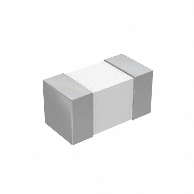
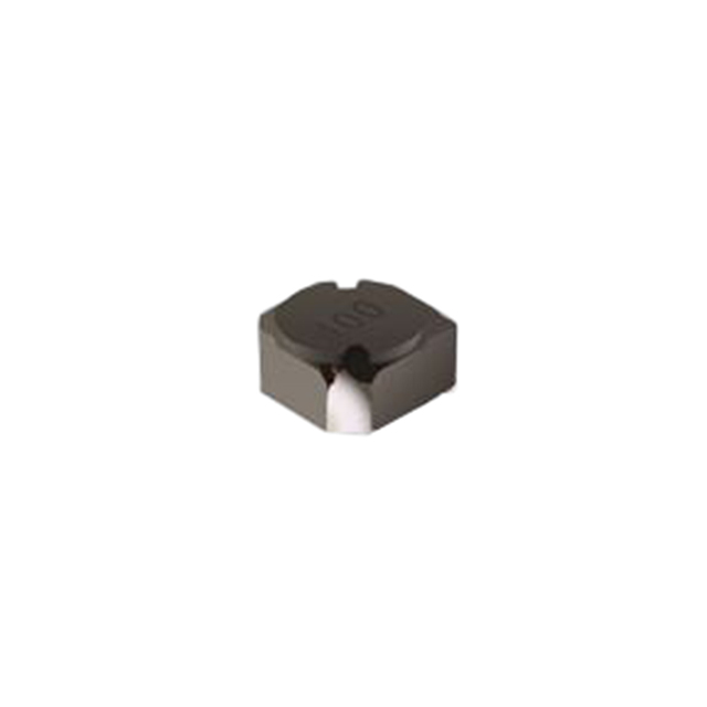
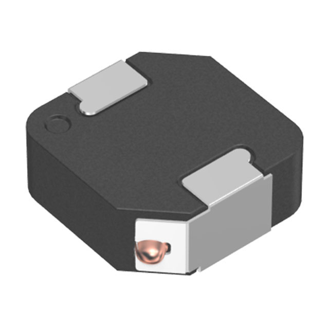
5) Components on Flexible Printed Circuits (Popular Packages & “Models”)
A flexible printed circuit isn’t just copper. It can carry real components—if you select packages that tolerate flex assembly and strain. The biggest principle: keep heavy, tall, and stiff parts off dynamic bend zones.
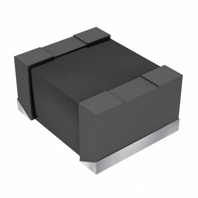
Passive components (common “hot” packages)
- Resistors and capacitors in 0402, 0201, and 01005
- Thin-film resistor arrays for controlled impedance / matching
- ESD/TVS arrays in DFN / ultra-small packages near connectors
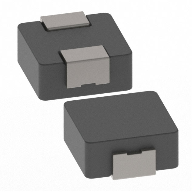
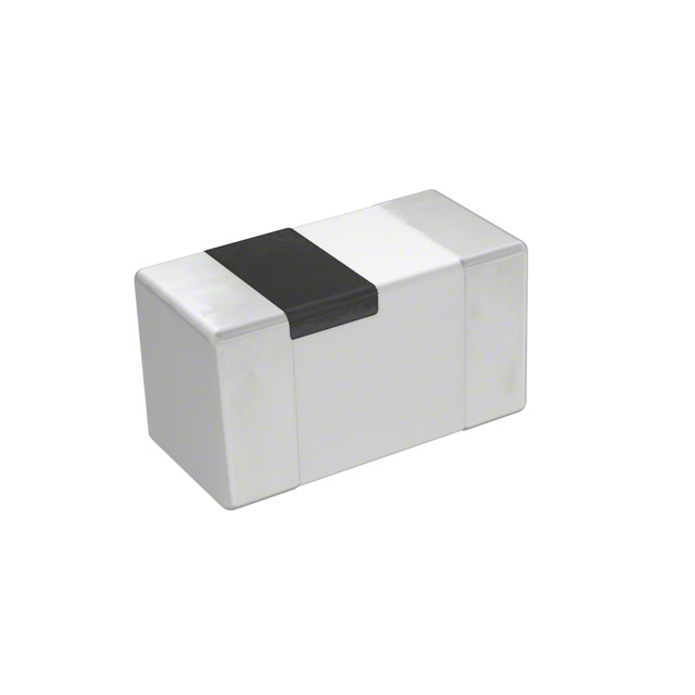
IC packaging styles often used on flexible printed circuit designs
- WLCSP / CSP for ultra-compact sensors and controllers
- Ultra-thin QFN (often paired with stiffeners)
- COF (Chip-on-Flex) for display driver integration
- COG (Chip-on-Glass) in display ecosystems where the flex acts as interconnect
Component placement strategy on a flexible printed circuit often follows an unwritten rule: the flex should move, the components should not. This leads to a natural separation between “flex zones” and “rigid zones,” even on a single-layer flexible printed circuit. Designers who ignore this separation usually discover the problem not during assembly, but later during reliability testing—or worse, in the field.
Ultra-small passives such as 0201 and 01005 are not chosen for fashion reasons. Their reduced mass lowers solder joint stress during bending and vibration. On a flexible printed circuit, physics rewards smaller footprints. If your assembly process can support them, they can be a meaningful reliability win.
Popular “system-level models” in flex-heavy products (no manufacturers)
In real products, engineers commonly design a flexible printed circuit around building blocks like: OLED display driver COF modules, camera module flex tails with high-speed differential lanes, touch controller flex front-ends, battery interconnect flex assemblies, and sensor flex harnesses using WLCSP IMU/pressure/optical sensors. These are the practical “models” that show up again and again because they match real packaging constraints.
The practical design habit: decide early which region of the flexible printed circuit is “electronics” (components, connectors, stiffeners) and which region is “mechanics” (bending). Then enforce that boundary in layout reviews like it’s a safety requirement—because in many products, it is.
6) Consumer Electronics Use Cases (Phones, Foldables, Wearables)
Consumer electronics is where the flexible printed circuit became a superstar—quietly. Smartphones rely on flexible printed circuit designs for display interconnects, camera modules, antennas, button arrays, and sensor routing. You don’t see the flexible printed circuit in marketing photos, but you absolutely see its impact in thinness, bezel size, and assembly simplicity.
Foldables: where bend life becomes the plot
In foldable devices, a flexible printed circuit often lives near hinges and moving mechanisms. That makes bend radius, copper choice, and coverlay design absolutely critical. In other words: this isn’t a “copy last project” moment.
In smartphones and foldables, the flexible printed circuit often becomes the limiting factor for industrial design ambition. Display size, hinge geometry, and fold angle must ultimately respect copper fatigue limits. Many design iterations in modern devices are driven not by display technology—but by flexible printed circuit survivability.
Wearables: curves + sweat + motion
Wearables use flexible printed circuit layouts to wrap around enclosures, connect sensors, and survive daily motion. It’s not glamorous engineering, but it’s the difference between “works in the demo” and “survives a year.”
Wearables also push material and sealing constraints: skin contact, sweat, cleaning chemicals, and tight sealing gaskets. A flexible printed circuit that passes electrical tests can still fail mechanically if it chafes against housing edges or is pinched by an enclosure seam. In consumer products, the flexible printed circuit must survive real life, not just the lab.
.png?x-oss-process=image/auto-orient,1/quality,q_70/format,webp)
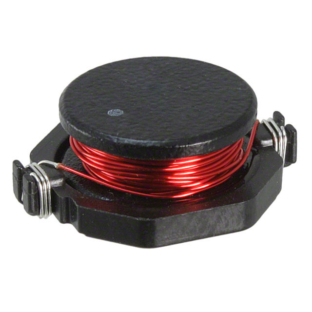
7) Automotive & Industrial Use Cases (Cameras, Displays, Motion)
In automotive and industrial systems, a flexible printed circuit grows up fast. Requirements include temperature swings, vibration, EMI, and long service lifetimes. Flex is used in camera modules, in-cabin displays, sensor harnesses, and compact control assemblies.
High-speed signaling on flexible printed circuit
High-speed differential pairs (camera/display links) can be routed on a flexible printed circuit with controlled impedance, but it requires careful stack-up, reference planes, and routing discipline—plus an EMI strategy. The penalty for getting it wrong is not just a failed eye diagram; it’s intermittent behavior that appears only at certain bend angles or temperatures.
In automotive environments, flexible printed circuit designs must tolerate not only vibration and temperature extremes, but also long service lifetimes. A flexible printed circuit that performs perfectly in a consumer product for two years may fail prematurely in a vehicle expected to last fifteen. That changes how engineers think: you design for fatigue margin, not “just meeting spec.”
Industrial designs often add additional reinforcement layers, redundant routing, or more conservative bend radii specifically for extended lifetimes. In this context, flexible printed circuit design becomes reliability engineering rather than packaging optimization. The flexible printed circuit is no longer a convenience—it’s a critical subsystem.
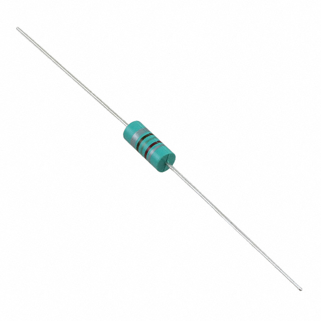
8) Design Rules That Make or Break a Flexible Printed Circuit
Designing a flexible printed circuit is part electrical engineering, part mechanical engineering. Ignore either side, and failures show up later—often after you’ve built enough units that “fixing it” becomes expensive.
Bend radius: the non-negotiable rule
Every flexible printed circuit has a minimum bend radius. Violating it can cause copper cracking, delamination, or intermittent faults. Treat bend radius as a hard design constraint, not a suggestion.
A useful mental model: tighter bends multiply stress at copper edges, pad corners, and any geometric discontinuity. If you can reduce stress concentration with geometry (fillets, gradual transitions), you often gain life without changing materials.
Routing through bend zones
- Route traces perpendicular to the bend direction when possible
- Avoid sharp corners; use arcs/fillets
- Use teardrops and stress-relief patterns
- Stagger traces across layers to reduce stress concentration
Where you place components matters
Keep components and vias out of dynamic bend areas when possible. If a flexible printed circuit must carry components near flex zones, stiffeners and mechanical constraints become part of the design.
One of the most common mistakes engineers make is assuming that electrical rules automatically translate to flex layouts. In reality, mechanical stress concentrates at vias, pads, and trace transitions. Even perfectly simulated electrical layouts can fail mechanically if stress relief is ignored.
Experienced flexible printed circuit designers often visualize copper as a metal spring rather than “just a conductor.” If it looks like it would crack when bent by hand, it probably will—eventually.
Practical reality: The fastest way to shorten flexible printed circuit life is to place a connector or stiff component right where the product wants to bend. The circuit will flex anyway—just not the way you intended.
Bonus design habits that pay off
- Define a “neutral bend axis” zone: keep critical traces away from the outermost stretch/compress edges.
- Avoid via clusters near bends: vias are stress concentrators; treat them like cracks waiting for a reason.
- Use gradual pad-to-trace transitions: sharp geometry creates localized strain.
- Plan strain relief: where the flex enters a connector or housing, add mechanical support or a stiffener.
.png?x-oss-process=image/auto-orient,1/quality,q_70/format,webp)
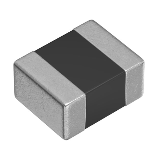
9) Flexible Printed Circuit Assembly: Yield & Process Tips
Assembly is where many flexible printed circuit projects stumble. Flex moves. Flex warps. Flex hates being treated like a rigid panel. Common production techniques include temporary carriers, fixtures, and controlled profiles to keep the flexible printed circuit stable through reflow.
Common assembly challenges
- Movement during pick-and-place and reflow
- Warp and curl affecting coplanarity
- Tombstoning on tiny passives
- Connector coplanarity and solder joint stress
Assembly yield on flexible printed circuit projects often improves dramatically once teams accept that flex requires different production psychology. Temporary carriers, panelization strategies, and handling procedures are not optional extras—they are part of the design.
Many early failures attributed to “bad flex quality” are actually caused by uncontrolled handling during assembly. Treating a flexible printed circuit gently is not superstition; it is process engineering. If your assembly line is tuned for rigid boards, expect a learning curve—and plan for it.
Connectors used with flexible printed circuit tails
Typical solutions include ZIF-style connectors, board-in connectors, and reinforced edge contacts—chosen based on thickness, cycle life, and assembly flow. The connector isn’t just a “part choice.” It dictates mechanical reinforcement, insertion force limits, and how your flexible printed circuit is handled in production.
Practical production tips that save headaches
- Carrier boards: keep the flexible printed circuit flat and stable through printing, placement, and reflow.
- Panelization planning: build in tabs, tooling holes, and safe handling edges.
- Post-reflow handling: avoid bending near solder joints until fully cooled and supported.
- Inspection strategy: verify not only solder joints but also coverlay alignment and stiffener adhesion.
10) Reliability Testing for Flexible Printed Circuits
A flexible printed circuit is often expected to survive mechanical stress that would destroy a rigid board. Reliability validation typically includes:
- Dynamic bend cycling (often the most revealing test)
- Thermal cycling
- Vibration testing
- Humidity exposure
- Connector insertion/removal cycling (if applicable)
If your flexible printed circuit is part of a hinge mechanism, bend-cycle testing isn’t optional. It’s the season finale.
Dynamic bend testing often reveals failure modes that static inspection cannot predict. Cracks may initiate invisibly under solder joints or within copper grains long before electrical failure is measurable. This delayed failure behavior is what makes flexible printed circuit reliability testing both frustrating and essential.
Teams that skip or shorten bend-cycle testing usually pay for it later—often after product launch, when fixes are most expensive. A helpful approach is to test at multiple bend radii (including worst-case assembly bends), multiple temperatures, and with realistic cable/connector constraints, because the flexible printed circuit rarely flexes in isolation inside a real product.
What “good” looks like in test planning
- Representative bending: match the product’s real bend direction and constraint points.
- Instrumentation: log intermittent opens, resistance drift, and signal integrity changes—not just “pass/fail.”
- Root-cause readiness: plan how you will inspect failures (microscopy, cross-sectioning) before testing starts.
.png?x-oss-process=image/auto-orient,1/quality,q_70/format,webp)
11) Cost Myths and System-Level Trade-Offs
Yes, a flexible printed circuit often costs more per unit than a rigid PCB. But system-level cost can drop because:
- Fewer connectors and cables are needed
- Assembly steps can be reduced
- Space and mechanical complexity may shrink
- Reliability can improve when interconnect count drops
Comparing only the flexible printed circuit unit price is like judging a movie by one scene. The full system matters.
Flexible printed circuit cost discussions often ignore logistics and quality. Reduced assembly steps, faster final assembly, and lower warranty return rates all contribute to total cost of ownership. When evaluated correctly, a flexible printed circuit frequently lowers overall program cost despite higher unit pricing.
This is especially true in products where manual cable routing would otherwise dominate labor cost, or where connector failures would create expensive service calls. In those cases, the flexible printed circuit is not “premium”—it’s insurance.
Where cost can sneak up
- Tight tolerances: fine pitch + controlled impedance + tight registration increases fabrication complexity.
- Assembly fixtures: carriers and tooling add cost but often pay back through yield.
- Reliability margin: better copper/stackup choices may cost more but reduce field failures.
12) The Future of Flexible Printed Circuit Technology
The flexible printed circuit isn’t slowing down. Trends include thinner substrates, higher-density routing, better EMI strategies, and more integration with antennas and sensors. As devices continue to shrink, bend, and move, the flexible printed circuit remains a core building block.
Future flexible printed circuit developments increasingly blur the line between interconnect and function. Antennas, sensors, and even energy-harvesting elements are being integrated directly into flexible printed circuit layouts. This convergence elevates flexible printed circuit design from “interconnect engineering” to “system architecture.”
As product forms evolve toward thinner, softer, and more organic geometries, the flexible printed circuit will remain foundational—not transitional. The teams who win will be the ones who treat flex as a first-class design domain (mechanical + electrical + process), not a late-stage routing patch.
FAQ: Flexible Printed Circuit Questions
FAQ — Click to expand
What is a flexible printed circuit used for?
A flexible printed circuit is used where products need thin, bendable interconnects: smartphones, wearables, cameras, displays, medical devices, automotive modules, and industrial equipment with motion or tight packaging.
Is a flexible printed circuit the same as a flex cable?
Often people use the terms interchangeably. In practice, a flexible printed circuit can act like a flex cable, but it may also carry components, controlled impedance traces, shields, stiffeners, and complex multilayer routing.
What is the biggest failure cause in flexible printed circuits?
The most common failure is mechanical fatigue: copper cracking or delamination due to an insufficient bend radius, poor stack-up choices, or placing vias/components in dynamic bend zones.
Can you place ICs and passives on a flexible printed circuit?
Yes. Many flexible printed circuit designs carry passives (0402/0201/01005) and ICs in compact packages (WLCSP/CSP, ultra-thin QFN), plus display-related formats like COF. The key is to avoid placing rigid components in dynamic bend regions without stiffeners and mechanical planning.
When should I use rigid-flex instead of a flexible printed circuit?
Use rigid-flex when you want rigid mounting areas for components plus integrated flex interconnects—often improving assembly and reliability at higher cost. Use a flexible printed circuit alone when you mainly need a thin, bendable interconnect or flex tail.
How do I design traces in a bend area?
Route traces perpendicular to the bend direction when possible, avoid sharp corners, use arcs/fillets and teardrops, and keep vias/components out of dynamic bend areas. Bend radius and copper type (RA vs ED) strongly influence reliability.
Does a flexible printed circuit help with reliability?
It can—by reducing connectors and interconnect points. But a flexible printed circuit only improves reliability if mechanical rules are followed. Poor bend planning can make reliability worse than a simple rigid+cable approach.
What’s the difference between static bend and dynamic flex?
A static bend flexible printed circuit is bent once during assembly and then stays in that shape. A dynamic flex flexible printed circuit bends repeatedly during use. Dynamic flex requires more conservative bend radius, better copper choice (often RA), and stricter avoidance of vias/components in bend zones.
Why do stiffeners matter on a flexible printed circuit?
Stiffeners localize flexing away from solder joints and connector interfaces. Without stiffeners, insertion forces and handling stress can crack solder joints or fatigue copper near pads. A well-placed stiffener helps the flexible printed circuit flex where you want it to—not where it will fail.

 FAQ
FAQ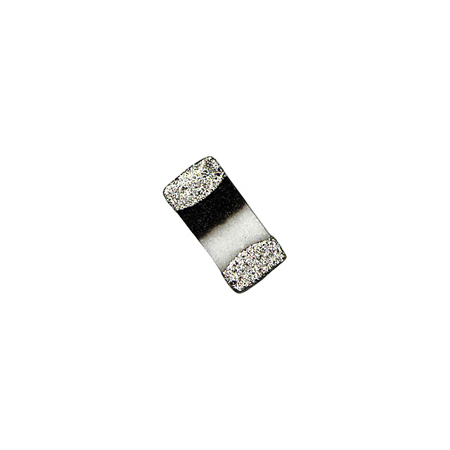


.png?x-oss-process=image/format,webp/resize,h_32)


