
 German
 Japanese
 Portuguese
 Korea
Korea
 Mexico
 Dutch
Dutch


Circuit Board Deep Dive: From Motorcycle ECUs to DIY Soldering

.png?x-oss-process=image/auto-orient,1/quality,q_70/format,webp)
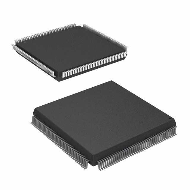
1. Circuit Board 101 – The Green City Behind Every Gadget
When you open a TV remote, a PlayStation controller, or the ECU of a motorcycle, you’ll see it: a flat, usually green plate filled with shiny paths, mysterious pads and tiny black rectangles. That, dear engineer (or curious binge-watcher), is the circuit board.
A circuit board, more formally called a printed circuit board (PCB), is the structural and electrical backbone of almost every electronic device:
- It holds components in place so they don’t rattle around like popcorn in a microwave.
- It routes signals between chips, sensors, connectors and power rails.
- It handles power distribution, grounding, and EMC much more elegantly than a jungle of point-to-point wires ever could.
Imagine the circuit board as the city in a sci-fi series like The Mandalorian:
- The copper traces are highways.
- Vias are wormholes between levels.
- ICs are skyscrapers full of secret things.
- Resistors, capacitors and diodes are the everyday workers making sure the city actually functions.
Without a circuit board, your fancy microcontroller, MOSFETs and sensors are just expensive Lego pieces with nowhere to snap in.
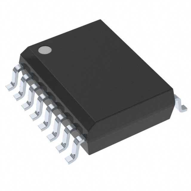
2. What Exactly Is a Circuit Board Made Of?
At a distance, every circuit board looks like a green rectangle. Up close, a modern PCB is a layered cake of materials and design rules.
2.1 The basic stack-up
A typical rigid circuit board consists of:
- Substrate – usually FR-4 fiberglass epoxy. It provides mechanical strength and basic insulation.
- Copper layers – thin sheets of copper laminated on one or more sides of the substrate. These form the traces, planes and pads of the circuit board.
- Solder mask – the green (or red, blue, black) coating that protects copper from oxidation and stops solder from bridging during assembly.
- Silkscreen – those white legends: reference designators, logos, polarity markers, test labels.
- Vias and plated through-holes – tiny drilled holes with copper plating that connect layers of the circuit board.
Higher-end circuit boards add more nuance:
- Controlled-impedance traces for high-speed signals.
- Power and ground planes to keep noise low and routing clean.
- Blind and buried vias for dense BGA layouts (FPGA, CPU, SoC).
- Special substrates (Rogers, polyimide, ceramics) for RF, high-temperature or automotive environments.
2.2 Copper weight and trace width
When you design a circuit board, you don’t just splash copper everywhere. You choose:
- Copper weight (e.g., 1 oz/ft², 2 oz/ft²) – thicker copper for higher current.
- Trace width & spacing – to safely carry current and meet the manufacturer’s capabilities.
- Clearance – safe distance between high-voltage nets and other copper.
That’s why a power converter board with big MOSFETs and shunt resistors looks chunky, while a smartphone logic board is a dense labyrinth of hair-thin traces.
.png?x-oss-process=image/auto-orient,1/quality,q_70/format,webp)
3. Types of Circuit Board: From Simple to Cinematic Universe
Just like the streaming platforms discovered that “one show fits all” doesn’t work, hardware designers know there’s no single PCB to rule them all. Different devices need different circuit board technologies.
3.1 Single-sided and double-sided circuit boards
Single-sided circuit board
- Copper only on one side.
- Cheap and easy to manufacture.
- Great for power supplies, basic toys, simple LED boards.
Double-sided circuit board
- Copper on both sides of the board, with plated vias connecting them.
- Huge step up in routing density.
- Common in audio gear, mid-complexity industrial control, general embedded boards.
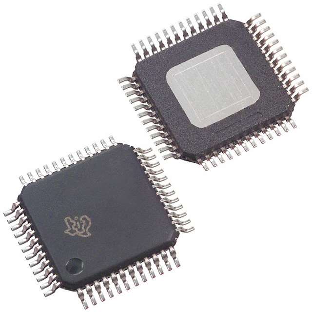
3.2 Multilayer circuit boards
Modern electronics love multilayer circuit boards: 4, 6, 8, 10 layers or more.
- Internal layers dedicated to ground and power reduce EMI and voltage drop.
- Signal layers support dense routing for microcontrollers, FPGAs, DDR memory and high-speed interfaces (PCIe, HDMI, USB-C).
- BGAs with hundreds of pins are only practical on multilayer boards.
Think of a multilayer circuit board as a multi-level cyberpunk city: signals dive underground, pop up on another level, sneak under other traces, then surface exactly where they’re needed.
3.3 Flexible and rigid-flex circuit boards
Flexible circuit board (flex PCB)
- Built on thin polyimide instead of rigid FR-4.
- Can bend and fold – perfect for camera modules, wearables, folding phones.
Rigid-flex circuit board
- Rigid area holding components + flex tails connecting them.
- Common in laptops, drones, automotive clusters, medical devices.
Whenever you see something compact and oddly shaped – like an action camera or a smartwatch – you can bet there’s a flex or rigid-flex circuit board hiding inside.
3.4 High-density interconnect (HDI) circuit boards
As chips get smaller and IOs multiply (hello, BGA FPGAs and SoCs), we meet HDI circuit boards:
- Microvias (laser-drilled), often stacked or staggered.
- Very fine trace and space (down to 3/3 mils or even less).
- Used in smartphones, tablets, high-end networking equipment, automotive ADAS.
This is where PCB design starts to feel like plotting a heist in Money Heist: one wrong via and the whole plan collapses.
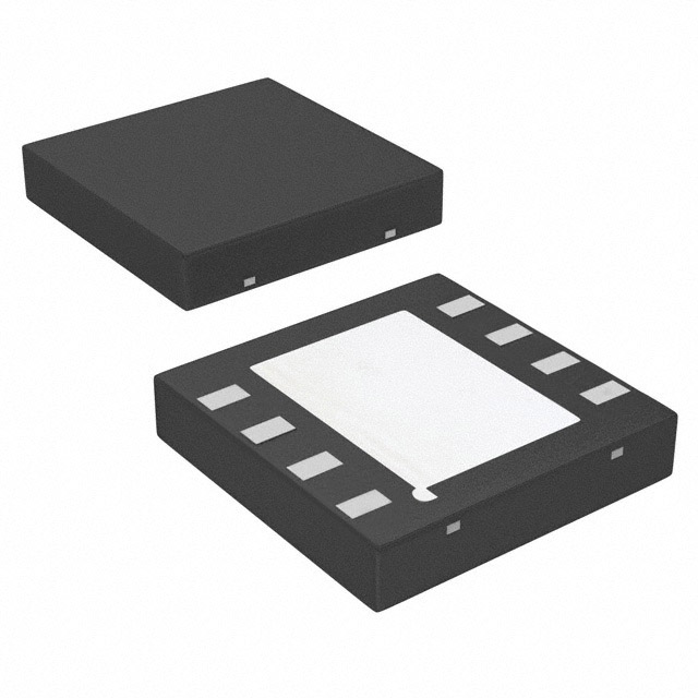
4. Anatomy of a Circuit Board: Components & Layout
A circuit board is nothing without components. Let’s zoom into what actually lands on that green city.
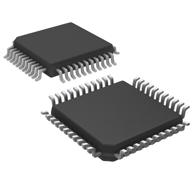
4.1 SMD vs through-hole
- Through-hole components use leads that pass through drilled holes in the circuit board, soldered on the opposite side.
- Strong mechanical bond, great for connectors, big capacitors, relays.
- Surface-mount devices (SMD/SMD) sit directly on pads on the same side.
- Ideal for automated assembly and high density.
- Includes resistors, capacitors, ICs, MOSFETs, diodes, regulators, and more.
Modern circuit boards usually mix both: SMD for dense logic and passives, through-hole for connectors, big inductors or power parts.
4.2 Critical layout zones
On a well-designed circuit board you’ll often recognise:
- Power section – regulators, MOSFETs, power inductors, shunt resistors.
- Digital brain – microcontroller, FPGA, memory, clock circuitry.
- Analog front-end – op-amps, ADCs, filters, sensor connectors.
- RF / high-speed – controlled-impedance traces for antennas, Ethernet, HDMI, USB, PCIe.
A good layout keeps noisy switching nodes away from fragile analog circuits, and ensures the circuit board’s ground and power planes form a stable reference for all the ICs.
.png?x-oss-process=image/auto-orient,1/quality,q_70/format,webp)
5. What Kind of Circuit Boards Are Found in Motorcycles?
Motorcycles may look like pure mechanical beasts, but modern bikes are full of circuit boards hiding under the fairings. Think of them as the MOTU (Masters of the Universe) running the show backstage.
5.1 Engine control unit (ECU) circuit board
The ECU is the bike’s main brain:
- Microcontroller or automotive-grade SoC.
- Analog front-end for sensors: throttle position, crankshaft, MAP, O2, temperature.
- Injector and ignition drivers (high-current outputs).
- CAN/LIN transceivers for communication.
The ECU circuit board is usually:
- Multilayer (4–8 layers) with solid ground planes.
- Designed with automotive-qualified components (AEC-Q100, etc.).
- Protected against vibration, moisture, and temperature swings (-40 to +125 °C).
Conformal coating or potting is common to protect the ECU circuit board from condensation and fuel vapors.
5.2 Instrument cluster / dashboard circuit boards
Digital dashboards, TFT displays, and classic gauge clusters all have circuit boards:
- LED drivers for backlight and indicators.
- Stepper motor drivers for analog gauges.
- Microcontrollers or cluster controllers handling CAN messages.
- DC-DC converters to tame the 12 V system and transients.
These circuit boards live at the intersection of electronics and design: they must survive harsh conditions but also meet UX expectations straight out of a Fast & Furious movie.
5.3 ABS, traction control and safety module boards
Safety systems like ABS and traction control use dedicated modules:
- Pressure sensors, wheel speed sensors.
- Power MOSFETs and drivers for hydraulic pumps or valves.
- Robust power filtering (load dump, cranking, ESD).
Boards are usually heavily protected, full of TVSs, pi filters and thick copper pours to survive jump-starts, reverse battery, and road noise.
5.4 Lighting and accessory circuit boards
Modern motorcycles increasingly use:
- LED headlight / taillight circuit boards – aluminum-core MCPCBs for thermal management.
- Accessory controller boards – heated grips, USB chargers, Bluetooth modules, GPS trackers.
Here, the circuit board must combine decent power handling (for LEDs and heaters) with EMI-conscious design so it doesn’t confuse the ECU.
In short: the average modern motorcycle contains several specialised circuit boards, each tuned for its job but sharing a love of rugged components and bulletproof layout.
6. How to Make a Circuit Board (From Idea to FR-4 Reality)
“How to make a circuit board?” is one of those questions that ranges from “draw something on copper with a marker” to “spin a 12-layer HDI stack with DDR4 and PCIe.” Let’s walk through both hobby and professional perspectives.
6.1 The design flow: schematic to PCB
Regardless of complexity, the journey looks like this:
- Schematic capture
- Use tools like KiCad, Altium, Eagle, OrCAD or EasyEDA.
- Place symbols, define nets, assign values and references.
- Choose real components: resistors, capacitors, ICs, connectors, MOSFETs. - Footprint assignment
- Map each symbol to a footprint on the circuit board (SOIC, QFN, BGA, SMD resistors 0603 etc.). - PCB layout
- Define the board outline, layers, design rules.
- Place components strategically: keep power close, minimize loop areas, respect high-speed rules.
- Route traces, add planes, vias, test points, fiducials.
- Run DRC (design rule check) and ERC. - Generate outputs
- Gerber files, drill files, netlist, pick-and-place, BOM.
- These are the digital blueprints for your circuit board manufacturer and assembler.
6.2 Professional PCB fabrication
When you send your design to a board house, the circuit board travels through:
- Lamination of copper and prepreg layers.
- Drilling and plating of vias and through-holes.
- Photolithography for trace patterning.
- Etching to remove unwanted copper.
- Solder mask and silkscreen application.
- Final surface finish (HASL, ENIG, immersion silver, etc.).
- Electrical test and inspection.
You choose parameters like:
- Layer count (2, 4, 6…)
- Copper thickness (1 oz, 2 oz for power)
- Minimum trace / space
- Impedance-controlled layers
- Board thickness, color, panelization.
The result is a shiny, bare circuit board ready for component population.
6.3 DIY: how to make a circuit board at home (high-level)
For small prototypes you can still “roll your own” circuit board in the lab or garage. At a high level:
- Design your simple layout (single or double-sided) in CAD.
- Print or transfer the pattern (laser printer + toner transfer paper, UV-exposed photoresist, or even permanent marker for very simple boards).
- Etch the copper using a safe etchant such as ferric chloride or sodium persulfate (following all safety instructions, ventilation and disposal rules).
- Drill holes for through-hole parts.
- Tin or coat the pads to improve solderability.
- Populate components and solder.
Even for hobby work, wear gloves, eye protection and follow chemical disposal rules. A circuit board should not turn into your origin story as a Marvel villain.
.png?x-oss-process=image/auto-orient,1/quality,q_70/format,webp)
7. How to Solder an Electronic Circuit Board
If designing a circuit board is writing the script, soldering is filming the show. Done well, it’s almost relaxing. Done badly, it’s a horror reboot featuring lifted pads and cold joints.
7.1 Tools and materials
To solder an electronic circuit board you typically need:
- Temperature-controlled soldering iron or soldering station.
- Solder (lead-free SnAgCu or leaded SnPb where permitted).
- Flux (liquid or paste).
- Tweezers, side cutters, small pliers.
- Solder wick and/or desoldering pump for rework.
- Isopropyl alcohol and lint-free wipes for cleaning.
For more advanced work, a hot-air rework station or reflow oven is ideal, especially for QFN, BGA and small SMDs.
7.2 Through-hole soldering, step by step (high-level)
- Insert the component leads into the correct holes in the circuit board.
- Bend or slightly splay the leads on the back side to hold parts in place.
- Heat the pad and lead simultaneously with the iron tip for a second or two.
- Feed solder into the joint (not onto the iron).
- Remove solder, then iron, keeping the joint still while it solidifies.
Good joints on the circuit board look shiny and volcano-shaped, not dull blobs or spikes.
7.3 SMD hand-soldering tips
- Use a fine chisel tip and thin solder.
- Add flux generously to pads; flux is cheap, frustration is expensive.
- For small ICs, the drag soldering technique works well:
- Pre-tin one pad, place the IC, reflow that pad to hold it.
- Flood pins with solder + flux.
- Wick away excess solder, leaving clean joints.
For QFNs/BGAs, reflow or hot-air with solder paste and stencil is usually easier and safer for the circuit board.
7.4 Protecting the circuit board while soldering
- Don’t overheat pads; FR-4 delaminates if you linger too long.
- Keep the tip clean and tinned.
- Anchor high-current components (connectors, inductors) mechanically before soldering so they don’t stress the circuit board in use.
8. How to Clean a Circuit Board (Without Killing It)
Every circuit board eventually gets dirty: flux, dust, spilled coffee during a binge-watch of Stranger Things. Cleaning improves reliability and makes inspection much easier.
8.1 When should you clean a circuit board?
You should clean a circuit board when:
- Flux residues are visible around joints.
- There’s dust, grime or sticky contamination.
- You performed rework or hot-air repairs.
- The board was exposed to environment (smoke, humidity, minor spills).
8.2 Safe cleaning methods
Isopropyl alcohol (IPA, 90–99%)
- Industry standard for cleaning flux residues.
- Use a small brush, swabs or lint-free wipes.
- Work in a ventilated area, keep away from sparks.
Specialised PCB cleaners
- Flux removers, contact cleaners.
- Follow manufacturer instructions; some are aggressive to plastics.
Deionized water (for water-soluble flux)
- Only for boards designed for aqueous cleaning.
- Must be thoroughly dried afterwards (air, low-temperature oven, or controlled drying cabinet).
8.3 Methods to avoid or treat with extreme caution
- Household cleaners, acetone, strong solvents – can attack plastics, labels, conformal coating.
- Ultrasonic cleaners – useful in some professional contexts, but can mechanically stress components or crack delicate solder joints if misused.
8.4 Drying the circuit board
After cleaning, a circuit board must be completely dry:
- Blow off excess liquid with compressed air (oil-free).
- Let it air-dry; for critical boards, bake at low temperature (~50–60 °C) for a few hours.
- Don’t power up until you’re absolutely sure no moisture remains under ICs or connectors.
Cleaning is basically giving your circuit board a spa day—just don’t drown it.
.png?x-oss-process=image/auto-orient,1/quality,q_70/format,webp)
9. How to Extract Gold from Circuit Boards (Safely & Responsibly)
This is the part where DIY videos on the internet go full Breaking Bad. Yes, there is gold on many circuit boards. No, that doesn’t automatically mean you should start boiling chemicals in your garage.
9.1 Where the gold is on a circuit board
Gold appears on circuit boards mainly as:
- Thin plating on edge connectors.
- Bonding pads for IC wire bonds.
- Sometimes as part of ENIG finish (electroless nickel immersion gold).
The total amount of gold per small consumer circuit board is tiny – milligrams, not grams.
9.2 Why home gold extraction is risky
Recovering gold from circuit boards typically involves:
- Strong acids (nitric acid, hydrochloric acid, aqua regia).
- Sometimes cyanide-based processes in industrial operations.
- High-temperature smelting or incineration steps.
These processes can produce:
- Toxic fumes and gases.
- Hazardous liquids requiring specialized disposal.
- Serious environmental damage if mishandled.
Because of these risks, detailed, step-by-step chemical recipes are not recommended for home use. Many countries also regulate such chemical handling and e-waste processing.
9.3 Safer, high-level options
If you’re interested in gold recovery from circuit boards:
- Use certified e-waste recyclers
- Many companies collect discarded electronics and recover metals in controlled industrial facilities.
- They use proper fume handling, scrubbers, and waste treatment. - Mechanical pre-processing (high-level)
- Boards are shredded, metals and non-metals separated.
- Ferrous, non-ferrous and precious metal fractions are sorted. - Professional metallurgical processes
- Pyrometallurgical (smelting, refining).
- Hydrometallurgical (chemical leaching under controlled conditions).
- Electrorefining and precipitation.
9.4 Hobby-friendly alternatives
If you’re more curious about learning than becoming a precious-metal tycoon:
- Tear down old circuit boards and identify where gold plating is used – it’s great educational material.
- Focus on component harvesting instead of metal extraction: salvage connectors, relays, transformers, inductors, heat sinks and even some ICs.
- Donate large quantities of scrap circuit boards to professional recyclers and, in some regions, get a small credit or compensation.
Bottom line: yes, there’s gold in circuit boards, but the safe and environmentally responsible path is to work with professionals, not recreate a chemistry thriller in your kitchen.
10. Circuit Board Design Tips for Reliable Hardware
Whether you’re building a motorcycle ECU, a gaming keyboard or a LiDAR module, well-designed circuit boards share common traits.
10.1 Power integrity first
- Use solid ground planes and well-planned power planes.
- Keep decoupling capacitors as close as possible to IC power pins.
- Use wider traces or planes for high-current paths, and consider 2 oz copper for high-power boards.
10.2 Respect return paths
Every signal on a circuit board has a return current:
- For high-speed and sensitive analog, the return wants the path of least impedance, often directly under the trace on a solid reference plane.
- Avoid splitting planes or forcing return current through long detours – this creates EMI and crosstalk.
10.3 Separate noisy and quiet circuits
- Keep switching regulators, motor drivers and high-current MOSFETs away from low-level analog and RF sections.
- Route noisy traces on different layers or in different “zones” of the circuit board.
10.4 Plan for manufacturability and testing
- Add test points for important nets.
- Use consistent designators and clear silkscreen labels.
- Confirm that component packages, pad sizes and orientations are compatible with your assembly line (or your own soldering skills).
10.5 Protect the circuit board’s future self
- Consider conformal coating or potting for boards used in harsh environments (motorcycles, automotive, outdoor IoT).
- Choose connectors and mechanical mount points that don’t stress solder joints.
- Select components with healthy derating for voltage, current and temperature.
A well-designed circuit board ages like a good series: it keeps working long after the first season hype fades.
.png?x-oss-process=image/auto-orient,1/quality,q_70/format,webp)
11. Circuit Boards & Pop Culture: Why PCBs Are the Real Main Characters
Every time a sci-fi show cuts to a “future device,” you’ll see glowing holograms, floating screens, maybe a quantum core. What you usually don’t see is the circuit board that actually makes such things possible.
In real life:
- The AR headset owes its magic to a flex-rigid circuit board wrapping around optics.
- The self-balancing bike in a cyberpunk movie relies on multiple control circuit boards talking over CAN.
- The IoT coffee machine you reboot between episodes of your favorite series contains Wi-Fi modules, power boards and control PCBs humming quietly.
So while on screen we’re obsessed with AI, robots and spaceships, the unsung hero is still the circuit board – the physical platform where electrons follow carefully etched paths to make all of that work.
12. Conclusion: Think in Circuit Boards, Not Just Circuits
We’ve walked through:
- What a circuit board is and why it’s the central stage for electronic components.
- Different types of circuit boards: rigid, flex, multilayer, HDI.
- The role of circuit boards inside motorcycles – ECUs, clusters, safety modules, lighting.
- How to make a circuit board, from schematic to manufacturing (and high-level DIY).
- How to solder an electronic circuit board so it looks professional instead of cursed.
- How to clean a circuit board safely to keep it reliable.
- Why extracting gold from circuit boards is best left to professional recyclers.
- Design tips to keep your circuit board stable, manufacturable and future-proof.
If you start thinking in terms of circuit boards rather than loose components, your designs will automatically become:
- Easier to assemble, test and debug.
- More robust in the real world (heat, vibration, EMI, spills, late-night firmware updates).
- Friendlier to manufacturing partners, and easier to scale from prototype to production.
The next time someone waves a bag of parts and says, “Can you build this gadget?”, you can smile and reply:
“Sure. But first, let’s design the circuit board that makes all these parts play nicely together.”
Circuit Board FAQ
Q1. Is a circuit board the same as a PCB?
Yes. In most engineering contexts, “circuit board” and “PCB (printed circuit board)” refer to the same thing: the laminated structure of copper and insulating material that holds components and routes signals. “Circuit board” is the more casual term; “PCB” is the formal one used in documentation and fabrication.
Q2. What’s the difference between a single-sided and a multilayer circuit board?
A single-sided circuit board has copper on only one side and is ideal for simple, low-cost designs. A multilayer circuit board stacks several copper layers with internal planes and signal layers, enabling high-density routing, better power integrity and lower EMI – essential for microcontrollers, FPGAs, DDR memory and high-speed interfaces.
Q3. Can I clean a circuit board with alcohol?
Yes, isopropyl alcohol (IPA 90–99%) is widely used to clean flux and light contamination from circuit boards. Apply with a brush or swab, work in a ventilated area, and make sure the board is completely dry before powering it. Avoid harsh household cleaners, acetone or unknown solvents that may damage plastics or coatings.
Q4. How do I know if a circuit board is damaged?
Visual signs include burnt areas, cracked or lifted pads, broken connectors and corroded traces. Electrically, a damaged circuit board may show short circuits, open connections or unstable behavior. A multimeter, continuity tests, and comparing to a known-good board are common ways to diagnose circuit board damage.
Q5. Is it worth extracting gold from old circuit boards at home?
Usually not. The amount of gold in a typical consumer circuit board is very small, and recovering it safely requires strong acids, controlled processes and proper waste treatment. For safety and environmental reasons, it’s better to send scrap circuit boards to certified e-waste recyclers who handle metal recovery professionally.
Q6. Can I reuse components from an old circuit board in new projects?
Yes, many components can be salvaged from old circuit boards with careful desoldering: connectors, relays, transformers, inductors, heat sinks and even some ICs. Check datasheets, inspect for damage, and clean the leads before reuse. This is a great way to learn and reduce electronic waste.

 FAQ
FAQ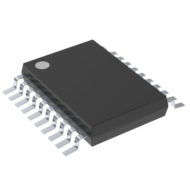


.png?x-oss-process=image/format,webp/resize,h_32)


