
 German
 Japanese
 Portuguese
 Korea
Korea
 Mexico
 Dutch
Dutch


Darlington Transistor: Big Gain, Bigger Personality

If House of the Dragon gave you epic alliances, the darlington transistor is the ultimate BJT alliance: two transistors teaming up so your tiny input can command large loads. This guide unpacks the darlington transistor with plain-English math, witty analogies, and design patterns you can paste into real products.
.png?x-oss-process=image/auto-orient,1/quality,q_70/format,webp)
1) What a Darlington Transistor Is (and Isn’t)
A darlington transistor—also called a Darlington pair—is a compound BJT where the emitter of the first transistor drives the base of the second. The result is a composite device that behaves like a single, very high-gain transistor. The darlington transistor shows up in relay and solenoid drivers, small DC motor drivers, lamp strings, and any place a microcontroller needs hefty current without a hefty base drive.
But the darlington transistor isn’t a free lunch. You stack base-emitter junctions (raising VBE(on)), you add saturation voltage, and you slow things down due to charge storage. Used wisely, it’s a star; used blindly, it turns your board into a slow, warm nightlight.
2) Math of a Darlington Transistor: Gain, VBE, and VCE(sat)
2.1 Overall Current Gain
For two BJTs with gains β₁ and β₂, the darlington transistor gain is:
β_total ≈ β₁·β₂ + β₁ + β₂ ≈ β₁·β₂ (when β ≫ 1)If each transistor has β ≈ 100, the darlington transistor ends up around 10,000—meaning base current can be tiny for a given collector current. That’s why a darlington transistor is beloved in microcontroller land.
2.2 Stacked VBE
Two silicon junctions in series yield VBE(on) ≈ 1.2–1.4 V (vs ~0.7 V for one BJT). Your logic pin must be able to forward-bias the darlington transistor despite this higher threshold—still easy from 3.3–5 V GPIO, but it changes resistor math.
2.3 Saturation Voltage
The darlington transistor often shows VCE(sat) of ~0.8–2.0 V at meaningful current; a single BJT might be ~0.05–0.3 V in similar conditions. That extra volt or so becomes heat (P ≈ I × VCE(sat)) and voltage lost across the switch—essential in low-voltage loads.
2.4 Base Resistor Sizing (Switching)
// Example: 5 V MCU → darlington transistor → 300 mA solenoid (with diode)
Target I_C = 0.3 A
Choose I_B_total ≈ I_C / 100 (Darlington allows tiny I_B; use margin)
I_B_total ≈ 3 mA
Assume V_BE_total ≈ 1.2 V → R_B ≈ (V_IO − V_BE_total)/I_B_total
R_B ≈ (5 − 1.2)/0.003 ≈ 1267 Ω → pick 1.2 kΩ or 1.3 kΩ
Add a base pulldown (e.g., 100 kΩ) if your input source floats at reset so the darlington transistor stays off.
.png?x-oss-process=image/auto-orient,1/quality,q_70/format,webp)
3) Speed Limits: Storage Time and Why Darlingtons Feel “Sticky”
The darlington transistor tends to store charge during saturation; when you turn it off, that stored charge must leave before current fully stops. The observed effect is a longer storage and fall time compared to a single BJT, and much slower than a MOSFET. In low-frequency applications (relays, solenoids, lamps), who cares. In PWM motor control or audio, this “stickiness” can mean heat and distortion.
- Mitigation: Avoid deep saturation by not over-driving the base excessively; add speed-up networks across base resistor; prefer arrays with built-in shaping.
- Topology: If you need kHz-range hard switching with low loss, the darlington transistor is probably not the lead. Use a MOSFET.
4) Design Recipes: Relays, Solenoids, and Motors
4.1 Relay Driver (Low-Side)
Put the relay coil to +V, the darlington transistor to ground. Add a flyback diode across the coil (cathode to +V). Compute base resistor with the VBE stack in mind. Many off-the-shelf parts (e.g., TIP120 family) include robust SOA; still, check coil inrush.
4.2 Solenoid Driver
Similar to relays but with longer on-times and higher duty. The darlington transistor’s higher VCE(sat) means more loss—ensure heatsinking if I × VCE(sat) is not negligible.
4.3 Small DC Motor (On/Off)
Works fine for simple on/off control. For PWM > ~1–2 kHz or when efficiency matters, switch to a MOSFET. The darlington transistor will run warm at higher duty and current because of that VCE(sat).
4.4 Lamp/Heater Strings
Non-inductive loads are friendly. Just mind dissipation at high current. A darlington transistor is perfectly happy here if you budget the heat.
.png?x-oss-process=image/auto-orient,1/quality,q_70/format,webp)
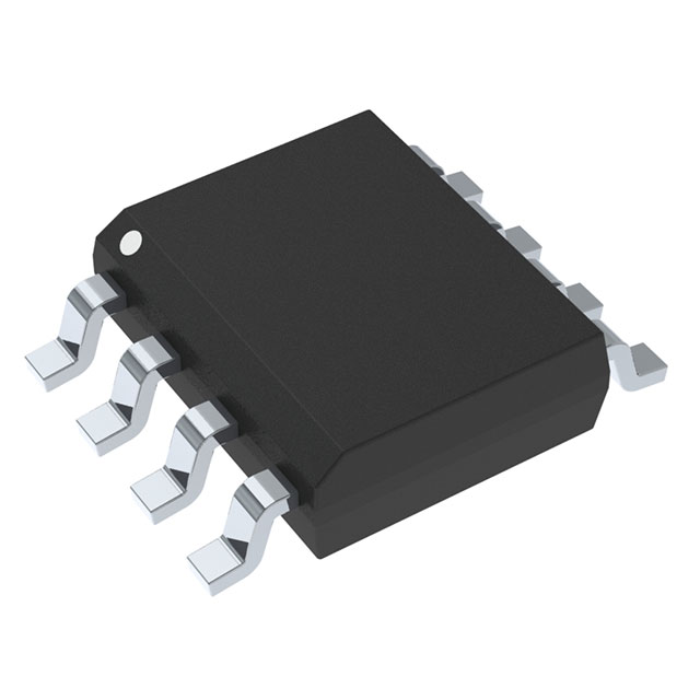
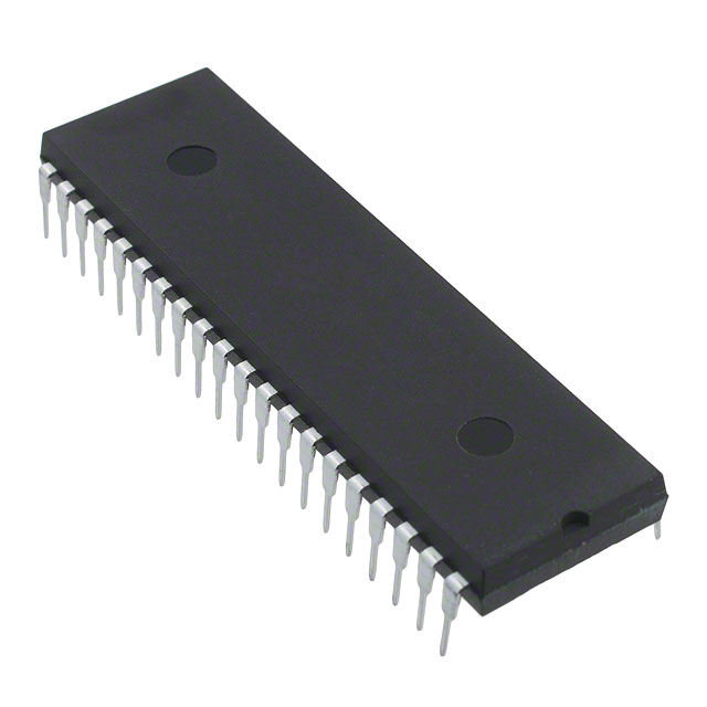
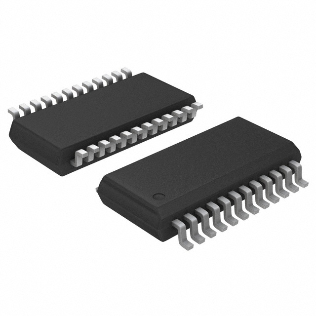
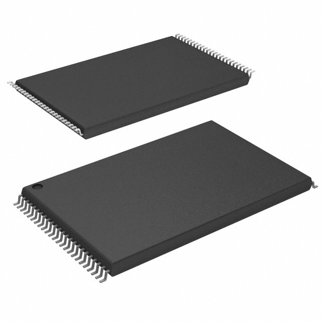
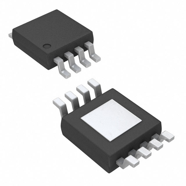
5) Darlington Arrays: ULN2003/ULN2803 and Friends
Why wire a single darlington transistor when you can have seven or eight in a neat DIP or SOIC? Integrated arrays (like the classic 7-channel and 8-channel open-collector NPN Darlington arrays) bundle base resistors and clamp diodes, so you can drive multiple relays/solenoids with one IC from a microcontroller.
- Open-collector outputs: They sink current; tie the load to +V.
- Input resistors inside: Easy MCU interfacing; check input current spec.
- Clamp diode pin: Some arrays expose a COM pin for the freewheel path—wire it to +V for inductive loads.
6) Layout, EMI, and Flyback: The Non-Negotiables
- Short loops: Keep the coil + diode + darlington transistor loop tight to cut ringing.
- Shared ground sanity: Big load currents should not flow through logic ground traces.
- Diode placement: Put the diode at the load if possible. Its job is to catch the inductive tantrum before it reaches the darlington transistor.
- Snubbers: For fast/longer wires, add RC snubbers to tame residual spikes and EMI.
.png?x-oss-process=image/auto-orient,1/quality,q_70/format,webp)
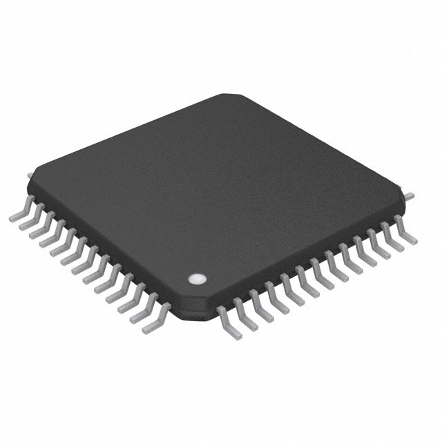
7) Thermal & SOA: Keeping a Darlington Transistor Cool
The math is simple and ruthless: P ≈ I × VCE(sat). Because VCE(sat) is higher, a darlington transistor runs warmer at a given current than a single BJT or MOSFET. Choose packages like TO-220/TO-247 for higher currents, and check the safe operating area (SOA) for pulses—relays and solenoids can surprise you on startup.
- Heatsink plan: If P > ~1 W continuous, plan for thermal pad/compound and a modest sink.
- Duty matters: A 10% duty may be fine bare, but 80% duty might demand a heatsink for the same current.
- Ambient and enclosure: Closed boxes make the darlington transistor sweat. Derate accordingly.
8) Darlington vs Single BJT vs MOSFET: Who Stars When?
| Tech | Strengths | Weaknesses | Use When |
|---|---|---|---|
| Darlington Transistor | Huge gain with tiny drive; easy MCU interface; arrays with diodes; simple BOM | High VCE(sat); slower switching; more heat at current | Relays/solenoids, on/off small motors, lamp strings, low-to-moderate speed |
| Single BJT | Lower VCE(sat); faster than Darlington | Needs more base current; gain varies a lot | Switching where loss must be lower, moderate drive available |
| MOSFET | Very low RDS(on); super fast; logic-level options | Gate handling/ESD; needs gate resistor & protection; can be pricier | PWM motors, high efficiency, higher frequencies, low voltage rails |
.png?x-oss-process=image/auto-orient,1/quality,q_70/format,webp)
9) Reading the Datasheet: Curves That Matter
- VCE(sat) vs IC: This sets heat and drop; scale current honestly.
- IB vs IC: See how little base current you actually need—then add margin.
- Switching: Storage and fall times define PWM limits for your darlington transistor.
- SOA: Respect pulse limits at your supply and inductance.
- Thermal RθJA/RθJC: Model your enclosure and heatsink; don’t forget ambient.
10) Troubleshooting: The Case of the Toasty Darlington
Symptoms → Likely Causes → Fix
- Driver runs hot: VCE(sat) × I too high → lower current, upgrade package, or move to MOSFET.
- Relay buzzes: Missing diode or weak drive → add flyback, increase base current; check coil voltage.
- Slow PWM response: Storage time → reduce frequency or switch tech; try speed-up cap across base resistor.
- Logic pin glitch turns on load: Floating input → add pulldown/pullup; shield long traces; add RC at input.
- Random resets nearby: Inductive kick EMI → tighten layout; diode at coil; add snubbers and ground discipline.

Related Articles
- ·MOSFET Transistor — The Practical, No-Drama Switch That Powers Modern Electronics
- ·MOSFET vs BJT Transistor — A Fun, Field‑Ready, No‑Nonsense Guide
- ·Transistor MTL2N2222AUB — The Playful, Practical, Pin‑Sharp Guide
- ·2N2222 Transistor: The Tiny Switch-Star That Still Steals the Scene
- ·Darlington Transistor: Big Gain, Bigger Personality
- ·BC547 Transistor: The Tiny NPN That Stars in a Billion Circuits
- ·NPN vs PNP Transistor: A Cinematic Showdown for Real-World Circuits
- ·Insulated Gate Bipolar Transistor (IGBT): The Dragon Rider of High-Power Circuits
- ·Transistor Symbol: The Blockbuster Guide (With Zero Boring)
- ·NMOS Transistor: The Silicon Speedster Powering 2025's Tech🚀
 FAQ
FAQ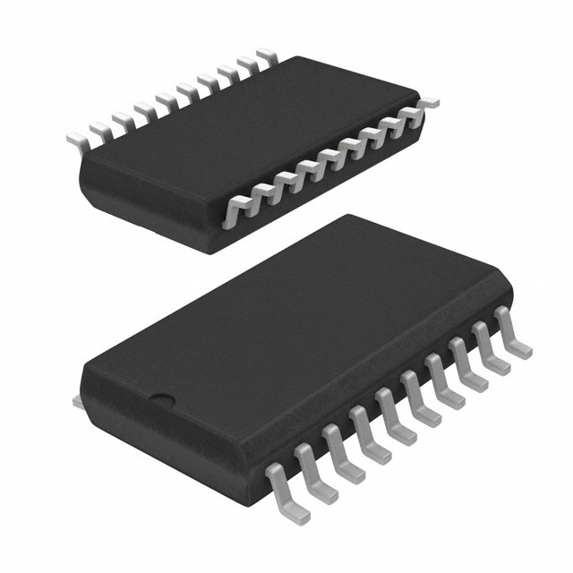


.png?x-oss-process=image/format,webp/resize,h_32)


