
 German
 Japanese
 Portuguese
 Korea
Korea
 Mexico
 Dutch
Dutch


HVAC Blend Door Actuator: The Tiny Robot That Turns Your Car Cabin into a Climate-Control Series Finale

If your car’s interior sometimes feels like season 1 of Game of Thrones on the driver’s side and Dune on the passenger side, you’re looking at the handiwork (or failure) of a very small, very underrated part: the HVAC blend door actuator.
On the outside, the HVAC blend door actuator looks like a boring black box with a connector and a few mounting ears. On the inside, it’s a compact electromechanical system built from electronic components: a DC motor, a gear train, a position sensor, and a tiny PCB with MOSFETs, resistors, and sometimes even its own little microcontroller.
In a previous deep dive we talked about the generic blend door actuator. Think of this article as the “expanded universe” episode: we zoom out to the full HVAC system and focus on the HVAC blend door actuator as part of a bigger, smarter, multi-actuator, multi-zone climate puzzle.
Grab a coffee, imagine your dashboard as a tiny spaceship cabin from The Expanse, and let’s see how the HVAC blend door actuator actually runs your personal weather show.
.png?x-oss-process=image/auto-orient,1/quality,q_70/format,webp)
1. HVAC Blend Door Actuator 101: The Hero Behind the Vents
Before we go full nerd on the electronics, we need a working definition that’s more precise than “that clicky thing behind the glove box.”
1.1 What Is an HVAC Blend Door Actuator?
An HVAC blend door actuator is an electrically driven actuator that moves the blend door (or blend flap) inside the heater/AC housing. That door controls how much air flows:
- Through the heater core (hot air)
- Around the heater core or through the evaporator (cold air)
…and blends these to achieve the cabin temperature you requested at the climate panel.
So in slightly more technical terms:
An HVAC blend door actuator is a closed-loop electromechanical servo system that positions an air-mixing door based on commands from the HVAC control module, using a DC motor, gear reduction, and position feedback.
The keyword here is HVAC:
- It’s tightly integrated with the Heating, Ventilation, and Air Conditioning system.
- It works alongside other actuators (mode door, recirculation door, sometimes fresh air doors).
- It responds not just to your manual knob, but to the whole climate strategy of the HVAC ECU.
1.2 HVAC Blend Door Actuator vs. “Plain” Blend Door Actuator
Practically, “blend door actuator” and HVAC blend door actuator usually refer to the same family of parts.
However, when people — or search engines — add that HVAC at the front, they are usually thinking about:
- How the entire HVAC system works together (sensors, ECUs, actuators)
- Diagnostics and replacement within the full HVAC context
- Electronic components that make the HVAC blend door actuator reliable and networked
If your previous reading was the “origin story” for a blend door actuator, this article is the spin-off series focused on its role in the wider HVAC universe.
2. How the HVAC Blend Door Actuator Fits into the Airflow Story
To understand the HVAC blend door actuator, picture your dashboard internals like a tiny industrial plant or a spaceship’s environmental control system (yes, pretty much Snowpiercer or The Expanse, just more plastic).
2.1 The Air Path in a Typical HVAC Module
Air inside a modern vehicle flows through:
- Air intake
- Outside air or recirculated cabin air, chosen by a recirc door actuator.
- Evaporator core
- Where refrigerant absorbs heat and dries the air.
- Heater core
- Where engine coolant warms the air.
- Blend door region
- Where the HVAC blend door mixes hot and cold streams.
- Mode doors
- Direct air to floor, panel vents, defrost, or combinations.
The HVAC blend door actuator sits right at step 4, deciding how much of the total airflow touches the heater core, how much bypasses it, and sometimes how it interacts with the evaporator.
2.2 Single-Zone vs Multi-Zone HVAC Systems
On a simple single-zone HVAC system, one HVAC blend door actuator controls temperature for the entire cabin.
On higher-end vehicles:
- Driver’s side has its own HVAC blend door actuator
- Passenger side has a separate HVAC blend door actuator
- Rear or third-row zones may have their own HVAC modules and actuators
That’s why:
- Driver: “Feels fine.”
- Passenger: “WHY IS IT A SAUNA?”
In multi-zone setups, each HVAC blend door actuator is a little robot managing its own climate district.
2.3 The Electronic Context Around the HVAC Blend Door Actuator
The HVAC blend door actuator doesn’t act alone. Nearby in the electronic ecosystem:
- HVAC ECU / Climate Control Module with microcontroller and CAN/LIN network
- Sensors:
- Cabin temp thermistors
- Sunload sensors
- Ambient temp sensors
- Evaporator and coolant temp sensors
- Other actuators:
- Mode door actuators
- Recirculation door actuators
- Sometimes auxiliary blower speeds, electric water pump control, etc.
The HVAC blend door actuator is the piece that turns all that sensor data into actual temperature change at the vents.
.png?x-oss-process=image/auto-orient,1/quality,q_70/format,webp)
3. Inside an HVAC Blend Door Actuator: Motors, Gears, Sensors & PCBs
Time to open the box. An HVAC blend door actuator is a neat little lab of mechanical and electronic design.
3.1 DC Motor: The Muscle
At the heart of the HVAC blend door actuator:
- A small 12 V brushed DC motor
- Automotive-grade, built to survive vibration and thermal cycling
- Controlled by an H-bridge so it can spin clockwise or counterclockwise
Electronic implications:
- Inductive load → needs flyback protection
- Stall current several times higher than running current → requires current limiting and robust MOSFETs
- Generates EMI → needs snubbers, capacitors, and careful PCB layout
3.2 Gear Train: The Torque Multiplier
The motor spins fast but with low torque. The HVAC blend door actuator needs slow, high-torque rotation.
- Multistage plastic gears (spur, sometimes helical)
- Reduction ratios like 20:1, 50:1, or higher
- Output gear connects to the blend door shaft (D-shaft, spline, or keyed)
Electronic side-note: gear ratio influences how the feedback loop and PWM driving are tuned. Higher reduction = more torque, smaller mechanical step for each motor step, but slower response.
3.3 Position Feedback: The “Eyes” of the HVAC Blend Door Actuator
The HVAC blend door actuator can’t just spin blindly; it needs to know where the door is. Common feedback technologies:
- Potentiometer feedback (very common)
- A rotary potentiometer on the output shaft
- Ends tied to 5 V and ground
- Wiper outputs a voltage (e.g., ~0.5–4.5 V) proportional to position
- HVAC ECU reads via ADC
- Hall-effect or magnetic encoder
- Magnet on the shaft, Hall sensor (or IC) on the PCB
- Outputs analog or digital position information
- No physical contact, better long-term reliability
- Smart actuator with built-in microcontroller
- Local microcontroller reads position sensor
- Talks to HVAC ECU over LIN bus
- Makes the HVAC blend door actuator a networked node, not just a dumb motor
All of these involve electronic components: resistors, reference voltages, ADC inputs, Hall ICs, pull-ups, filtering capacitors, and sometimes differential signaling.
3.4 The PCB: Where All the Electronics Live
Open an HVAC blend door actuator and you’ll usually find:
- Motor driver:
- Discrete N-channel and P-channel MOSFETs, or
- An integrated H-bridge driver IC with current limiting and diagnostics
- Protection circuits:
- Reverse-polarity protection
- TVS diodes or ESD diodes on signal lines
- RC snubbers across motor terminals
- Signal conditioning:
- Resistor dividers and filters for the potentiometer feedback
- Capacitors to smooth the ADC input
- Sometimes op-amps for buffering
- Logic:
- Simple versions: no MCU; HVAC ECU closes the loop
- Smart versions: tiny microcontroller inside the HVAC blend door actuator, speaking LIN and reporting fault codes
All of these electronic components are chosen for:
- Wide temperature range (−40 °C to +85+ °C)
- Vibration resistance
- Long life in a hot plastic box behind the dash
4. How the Car’s Brain Talks to the HVAC Blend Door Actuator
The HVAC blend door actuator doesn’t wake up in the morning and decide to rotate. It takes orders from the climate control module.
4.1 The Control Loop
The control loop looks like this:
- Inputs:
- Cabin temp sensor
- Sunload sensor
- Ambient temp sensor
- Evaporator temp, coolant temp
- Driver and passenger set temperatures
- Computation (inside the HVAC ECU):
- A control algorithm (often PID-like) decides the desired door position for each zone
- For example: 25°C target, high sunload, cool ambient → more warm mix
- Commands to the HVAC blend door actuator:
- In “dumb” actuators: PWM/H-bridge signals + analog feedback reading
- In “smart” actuators: LIN messages giving target position
- Actuator response:
- Motor spins
- Blend door moves
- Feedback signal updates
- Correction:
- MCU compares actual vs desired position
- Adjusts drive, slows down as it approaches target
- Stops when HVAC blend door actuator reaches the correct angle
This loop runs constantly whenever the ignition and climate system are active.
4.2 Networks: LIN and CAN
In more modern architectures:
- The main vehicle network is CAN
- The HVAC module is a node on CAN
- Individual HVAC blend door actuators may be on a LIN bus hanging off the HVAC controller
In that case, the HVAC blend door actuator has:
- A LIN transceiver IC
- A small MCU
- Local control firmware that:
- Handles diagnostics
- Implements inner control loops
- Reports errors and statistics
This trend makes the HVAC blend door actuator less of a simple spare part and more of a smart mechatronic module.
.png?x-oss-process=image/auto-orient,1/quality,q_70/format,webp)
5. When the HVAC Blend Door Actuator Goes Rogue: Real-World Symptoms
If this were a streaming series, this is where the plot twists start.
5.1 Wrong Temperature vs Knob Setting
Classic complaint:
“I set 22°C but it’s either freezing or boiling.”
An HVAC blend door actuator that doesn’t move, moves incorrectly, or reports wrong position can cause:
- Perma-cold (stuck in cold position)
- Perma-hot (stuck in hot position)
- Lukewarm everything (stuck somewhere in the middle)
5.2 One Zone Misbehaves, Others Fine
On multi-zone HVAC:
- Driver side: responds to temp changes
- Passenger side: always hot
- Rear: unknown chaos
This often points directly at one specific HVAC blend door actuator serving that zone.
5.3 Random Temperature Swings
As you drive, cabin temp evidence looks like:
- Hot → cold → warm → cold again, without you touching anything.
If the potentiometer inside the HVAC blend door actuator gets worn or dirty:
- Feedback signal becomes noisy
- The control loop “hunts” around the target
- You feel it as unpredictable temperature swings
5.4 Clicking, Ticking, and “Machine Gun” Noises
You start the car or change temperature; the dash responds with:
Click-click-click-click-click…
This usually means:
- The HVAC ECU is trying to move the HVAC blend door actuator to a new position
- Gears are stripped or out of sync
- The motor keeps turning, but the gear slips at the damaged teeth
From an electronics perspective, the motor driver is doing its job. Mechanically, the actuator is toast.
5.5 Recalibration Failures
Some cars give you a hidden HVAC self-test or recalibration mode.
If you run calibration and:
- Hear actuators moving but get error codes, or
- Calibration fails repeatedly
…one HVAC blend door actuator may not be reaching its endpoints or returning valid feedback.
6. Step-by-Step Diagnosis: From Driver Complaint to Multimeter Probing
Diagnosing an HVAC blend door actuator is like a detective episode: you start with vague complaints and end up with a suspect PCB in your hand.
6.1 Triage: Quick Non-Tool Checks
- Listen while changing settings
- Engine on (or at least ignition ON).
- Move temperature setting from coldest to hottest and back.
- Listen near the dash and glove box:
- Smooth, quiet movement = usually OK
- Clicking / grinding / no movement = suspicious actuator
- Compare zones
- On dual-zone/triple-zone: set extreme differences between sides.
- If only one side doesn’t follow changes, that HVAC blend door actuator is a prime suspect.
- Check modes and recirculation
- Make sure the symptom is really temp blend, not mode door or recirc door.
- A stuck mode door can feel like HVAC blend issues if air is going to the wrong outlets.
6.2 Scan Tool Diagnostics
With a decent OBD/scan tool that can talk to the HVAC module:
- Read DTCs (Diagnostic Trouble Codes):
- “Air mix door range/performance”
- “HVAC blend door actuator circuit”
- “LIN bus fault with actuator”
- View live data:
- Commanded door position vs actual feedback
- Actuator status (OK, stuck, no response)
- Sometimes current draw or error flags from smart actuators
6.3 Electrical Checks with a Multimeter
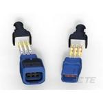
If you can access the actuator connector:
- Power & ground
- Key ON, HVAC active.
- Verify 12 V and good ground at the HVAC blend door actuator connector.
- No power/ground = wiring, fuse, or ECU issue, not necessarily the actuator itself.
- Feedback line (analog actuators)
- Identify the feedback pin (usually 3rd wire in 3-wire feedback).
- Measure voltage while the HVAC ECU moves the door.
- A healthy HVAC blend door actuator will produce a smooth, monotonic change in voltage.
- Jumps, dead spots, or flat-line readings = feedback sensor failure.
- Resistance checks (actuator disconnected)
- Check potentiometer resistance between ends and from wiper to ends as you turn shaft manually.
- Large dead ranges or erratic behavior confirm internal wear.
6.4 Bench Testing an HVAC Blend Door Actuator
Once removed from the car:
- Use a current-limited 12 V bench supply.
- Apply power and ground to the motor pins (consult pinout!).
- Verify that the HVAC blend door actuator turns in both directions.
- Monitor feedback voltage as you manually rotate the output shaft: it should change smoothly.
This bench test is extremely educational if you’re into electronics. You can see:
- How much current the motor draws
- How the feedback behaves
- Where the end stops are
.png?x-oss-process=image/auto-orient,1/quality,q_70/format,webp)
7. Replacement, Relearn, and Calibration Rituals
When diagnostics point clearly at the HVAC blend door actuator, it’s time for the replacement episode.
7.1 Accessing the Actuator
Depending on the car, replacing an HVAC blend door actuator ranges from:
- “Remove glove box, two screws, 15 minutes”
- To “Remove half the dashboard, plus some of your sanity”
Common patterns:
- Passenger-side actuators: accessible through glove box opening or under the dash.
- Driver-side actuators: hidden above pedals, behind metal braces.
- Rear-zone actuators: in the rear-quarter panels or behind interior trim.
Tools:
- 1/4" drive ratchet
- Long extensions
- Small metric or inch sockets
- Torx bits
- Trim removal tools
- Headlamp and patience
7.2 Removal Tips
- Disconnect battery if working near airbag wiring.
- Carefully unplug the connector; avoid pulling on the wires.
- Mark the actuator’s orientation and the door position if needed.
- Remove screws and gently wiggle the HVAC blend door actuator off the shaft.
Watch out for:
- Brittle plastic after years of heat
- Hidden screws behind ducts
- Dropping hardware into unreachable HVAC cavities (magnetic pickup tools are gold here)
7.3 Installing the New HVAC Blend Door Actuator
- Compare parts
- Same shape, connector, mounting, output shaft pattern.
- Many vehicles use multiple different HVAC blend door actuators, so part selection matters.
- Align the door
- If the blend door moved during removal, gently bring it to a neutral or expected position.
- Rotate the new actuator’s output shaft by hand to match.
- Mount and connect
- Install screws evenly and snug, not overtight.
- Plug connector firmly until it clicks.
7.4 Running Calibration / Relearn
May vary by manufacturer, but common patterns:
- Key-on/10–60 second wait
- Turn ignition ON, leave HVAC in AUTO or OFF.
- Don’t touch controls.
- System sweeps actuators to find end stops.
- Hidden HVAC test mode
- Press and hold specific button combinations.
- Follow on-screen or LED code prompts.
- System calibrates each HVAC blend door actuator.
- Scan-tool commanded relearn
- Use diagnostic tool to start “Actuator recalibration.”
- Monitor progress and errors.
After that, verify:
- Temperature responds correctly all across the range
- No unusual noises
- No new HVAC codes
8. Designing an HVAC Blend Door Actuator from an Electronics Perspective
If you’re on the engineering or supplier side, the HVAC blend door actuator is a perfect textbook problem in applied electronics and mechatronics.
8.1 Core Design Goals
An HVAC blend door actuator must:
- Survive 10+ years of thermal cycling, vibration, and occasional misuse
- Fit into a tight packaging envelope on the HVAC case
- Maintain accurate position over thousands of cycles
- Fail safely and predictably
- Be cost-effective in high volume
8.2 Electronic Component Selection
Key component classes:
- Motor driver stage
- Low-Rds(on) N-channel MOSFETs
- High-side drivers or H-bridge ICs
- Built-in current limiting and thermal shutdown if possible
- Position sensor
- Automotive-grade potentiometer or Hall sensor IC
- Tight tolerance, low drift over temperature
- Low noise with proper RC filtering
- Microcontroller (if “smart” HVAC blend door actuator)
- Small 8-bit or ARM Cortex-M0/M0+ MCU
- Built-in ADC for feedback
- LIN/UART peripheral
- Hardware watchdog
- Protection & EMC
- TVS diodes on supply and LIN/CAN lines
- Reverse-polarity protection FET or diode
- RC snubbers and EMI filters on motor leads
- PCB layout with short loops and good grounding
- Passive components
- Thin-film or thick-film resistors for dividers and pull-ups
- X7R/X8R MLCCs for filtering
- High-reliability connectors and gold-plated contact pins
8.3 Firmware and Control Strategy
For smart HVAC blend door actuators:
- Implement a local position control loop (PID or PI) in the MCU
- Filter feedback readings to avoid jitter from ADC noise
- Define safe behavior when LIN communication fails:
- Hold last known position
- Move to a safe default (e.g., mild blend) if commanded by requirements
Add diagnostics:
- Detect stall (high current + no motion)
- Detect sensor out-of-range or short/open
- Report standardized LIN diagnostic codes
Good firmware makes the HVAC blend door actuator easier to diagnose and safer in edge cases.
.png?x-oss-process=image/auto-orient,1/quality,q_70/format,webp)
9. Future Trends: Smart, Networked HVAC Blend Door Actuators
Modern vehicles are moving towards the “everything is smart” model. The HVAC blend door actuator is not exempt.
9.1 LIN-Connected Smart Actuators
Instead of routing multiple dedicated wires for every motor and sensor, OEMs are:
- Using a LIN bus from the HVAC controller
- Giving each HVAC blend door actuator an address and personality
- Letting each actuator:
- Close its own control loop
- Run self-tests
- Report errors and statistics
This reduces wiring complexity and makes the HVAC blend door actuator much more diagnosable.
9.2 Predictive Maintenance & Data Logging
With smart actuators, the car can track:
- Number of cycles
- Time spent near end stops
- Average current draw
That means the HVAC module could:
- Predict impending actuator failure
- Log events for service technicians
- Suggest maintenance before the HVAC blend door actuator leaves a driver stuck in “perma-hot” mode.
9.3 Integration with EV Thermal Management
In EVs and hybrids, cabin climate control is tightly tied to battery and power electronics cooling. The HVAC blend door actuator plays into:
- Heat pump operation modes
- Waste heat reuse
- More complex air routing strategies
As EV thermal systems get smarter, so will the electronics and firmware inside each HVAC blend door actuator.
10. How This Ties into the “Blend Door Actuator” Basics
If your site already has a blend door actuator article (the more general one), this HVAC blend door actuator guide is the natural sequel:
- The blend door actuator article can explain:
- Basic concept
- Generic construction
- DIY replacement
For that foundational overview, see “Blend Door Actuator: The Tiny HVAC Robot That Decides If You Live in Winterfell or Tatooine” .
- This HVAC blend door actuator article can go deeper into:
- Full HVAC system integration
- Electronics and networking (LIN/CAN, MCU, MOSFETs)
- Multi-zone and EV-specific behavior
Internal linking ideas:
- On the generic article, link to this page with anchor text like:
“For a deeper look at how the actuator interacts with sensors, ECUs and power electronics, see our HVAC blend door actuator electronics guide.” - On this HVAC-focused page, link back with:
“If you’re new to the topic and want a quick overview first, start with our blend door actuator basics explainer.”
That way, both articles form a small SEO cluster around “blend door actuator” and HVAC blend door actuator, and readers (plus search engines) can navigate between the conceptual intro and the electronics-heavy deep dive.
11. Quick FAQ for HVAC Blend Door Actuator Nerds
Q1: Is an HVAC blend door actuator different from a normal blend door actuator?
In most contexts they refer to the same part. “HVAC blend door actuator” just emphasizes its role in the Heating, Ventilation and Air Conditioning system, often in multi-zone and electronically controlled setups. For a more general, story-style explanation, you can also read our blend door actuator guide.
Q2: Why do modern HVAC blend door actuators use so many electronic components?
Because they’re no longer simple motors. They need precise positioning, diagnostics, communication (LIN/CAN), and robust protection against temperature, vibration, and electrical noise. That means MOSFET drivers, sensors, microcontrollers, and protection ICs.
Q3: What’s the most common failure mode?
Mechanically: stripped plastic gears or broken door shafts.
Electronically: worn potentiometer feedback or corroded connectors. Either one can make the HVAC blend door actuator misreport its position and confuse the HVAC ECU.
Q4: Can I swap an HVAC blend door actuator from a similar model?
Sometimes yes, often no. Even if the casing looks identical, the gear ratio, connector pinout, feedback scaling, or LIN configuration can differ. Always match part numbers and application data.
Q5: Does every car need calibration after replacing an HVAC blend door actuator?
Not every single one, but many modern systems do. A quick recalibration or self-test ensures the HVAC ECU learns the new actuator’s end stops and avoids constant clicking or incorrect temperatures.
Q6: How can I tell if the HVAC blend door actuator is “smart” (LIN-based)?
Check the wiring and documentation:
– More than 3–4 wires and a LIN label near the ECU or wiring diagram are clues.
– Smart actuators usually have identifiable LIN IDs and can be tested via a scan tool.
Q7: Can I reuse a failed HVAC blend door actuator for electronics projects?
Absolutely. With the right driver board (H-bridge and MCU), you can turn it into a high-torque servo for shutters, valves, robotics, or even your own DIY HVAC prototype.
The next time your cabin climate behaves like a crossover between Stranger Things and Mad Max, remember: there’s a tiny HVAC blend door actuator deep in the dash, fighting to keep your microclimate stable. And inside that little box is a surprisingly sophisticated cluster of motors, gears, sensors, and electronic components working together like a miniature mecha—one that deserves a lot more respect than its plain plastic shell suggests.

 FAQ
FAQ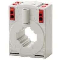


.png?x-oss-process=image/format,webp/resize,h_32)


