
 German
 Japanese
 Portuguese
 Korea
Korea
 Mexico
 Dutch
Dutch


Load Resistor: How to Choose, Size, and Troubleshoot the “Small Part” That Breaks Big Systems

This is not a resistor encyclopedia page. It’s a decision guide for engineers, buyers, and test teams who need to select a load resistor that behaves under real voltage, current, heat, tolerance, and supply-chain constraints—so you don’t pay later with browned PCBs, false pass/fail tests, unstable power loops, LED brightness drift, or “why does it work in the lab but not in the field?”
.png?x-oss-process=image/auto-orient,1/quality,q_70/format,webp)
One-Screen Answer (Selection + Procurement)
A load resistor is any resistor intentionally used to draw current, set a minimum load, bleed charge, shape a signal, or create a test load. The real selection question is: how much power will it dissipate in worst case, what temperature rise is acceptable, and how stable must the resistance be over time and temperature. Most failures are not “wrong ohms.” They’re wrong watts, wrong derating, and wrong thermal environment.
- You computed P = V²/R and P = I²R for worst case (not typical).
- You applied derating for ambient temperature and board heat.
- Your package and footprint can shed heat (copper area, airflow, enclosure).
- Your tolerance/TCR matches the function (measurement vs “just load”).
- You planned alternates without changing thermal behavior or footprint constraints.
Treating “same resistance value” as “same part.” A 10 Ω resistor can vary wildly by power rating, pulse capability, temperature rise, flame resistance, and long-term drift. That’s how a “drop-in substitution” turns a stable design into a hot, drifting, intermittently failing system.
Simple “minimum load” or bleed: prioritize safe wattage + temperature rise + flame behavior.
Power-supply testing / dummy load: prioritize power handling, heatsinking strategy, and pulse capability.
Signal loading / termination: prioritize tolerance, stability, and layout (noise/EMI).
LED current limiting: prioritize worst-case voltage, thermal drift, and surge/pulse limits.
What Is a Load Resistor (and What It Is NOT)?
“Load resistor” is a role, not a special component family. Any resistor becomes a load resistor when you intentionally use it to consume power or define a load condition. That role shows up in places like: (1) ensuring a converter or regulator stays in a stable operating mode, (2) discharging capacitors for safety, (3) setting LED current, (4) creating a known test load during validation, or (5) matching impedance in signal paths.
.png?x-oss-process=image/auto-orient,1/quality,q_70/format,webp)
- A resistor used to draw a controlled current or force a “known condition.”
- A way to stabilize some power supplies that need minimum load.
- A bleeder to discharge energy storage (caps) after power-off.
- A tool for testing: dummy loads, burn-in, calibration fixtures.
- Automatically “high power” (many loads are milliwatts—until surge and heat show up).
- Automatically “precise” (some loads can be 5% parts; others require 0.1% and low TCR).
- Automatically safe to swap (thermal and flame ratings matter).
- Just about ohms (the selection is usually dominated by watts and temperature rise).
Where Load Resistors Appear (and Why They’re Usually There for a Reason)
If you see a load resistor in a schematic, it’s often compensating for a real-world behavior: leakage, startup mode, measurement error, or stability under light load. Removing it may “work” in a short test and then fail in cold weather, production spread, or long-term aging. The fastest way to select correctly is to start from the use case.
Some DC/DC converters (or legacy regulator topologies) behave poorly at ultra-light load: output can rise, ripple increases, or control loops fall into skip/burst modes that trigger EMC or functional issues. A small load resistor forces the converter into a predictable region. The key selection variables are worst-case dissipation and temperature rise.
Used across capacitors or rails so voltage falls to a safe level after power-off. Here, the design goal is often a time constant (RC), not a specific load current. But the resistor still dissipates power during normal operation, and it must be safe under fault conditions.
Series resistors limit current into indicator LEDs or low-power lighting. The trap is ignoring worst-case supply tolerance, LED forward-voltage spread, and ambient temperature. LED circuits are where “it looks fine” becomes “too dim” or “too hot” after production variation.
A resistor used as a load in signal paths (e.g., termination) controls reflections and edge rates. Here, the “load resistor” is about impedance, tolerance, and parasitics. Choosing a physically different part can change high-frequency behavior even if the ohms match.
Validation rigs use load resistors to test supplies, batteries, chargers, and protection circuits. The selection is dominated by continuous power, pulse power, and cooling method. Fixture loads often fail because the engineer sized for “average” but the test includes startup surges or long holds at high dissipation.
Sometimes a “load” is there to define a default state, bias an amplifier stage, or discharge a node so ADC readings don’t float. These loads can be tiny in power but big in system behavior. Here, focus on noise, leakage, and accuracy when it impacts thresholds.
Decision Question: How Do You Size a Load Resistor (Without Guessing)?
The most reliable way to size a load resistor is to decide what you’re controlling—current, voltage drop, discharge time, or power draw—then calculate worst case. “Worst case” means the highest supply voltage, the lowest resistance tolerance, the hottest ambient (least cooling), and the longest time at load. If you skip that, the resistor won’t fail politely. It will drift, discolor, crack solder joints, or change your system behavior in ways that look like firmware bugs.
- Ohm’s law: I = V / R
- Power (voltage-based): P = V² / R
- Power (current-based): P = I²R
- Discharge time constant: τ = R·C (and V(t)=V0·e-t/RC)
- Define function: min-load, bleeder, LED, termination, test load.
- Pick target current or discharge time (or impedance).
- Compute R using nominal voltage; then compute worst-case P at max voltage.
- Apply derating for temperature + mounting conditions.
- Validate with a thermal test (board-level, enclosure-level, airflow-level).
Suppose a 12 V rail behaves better with a minimum 30 mA load. Then R = 12 V / 0.03 A = 400 Ω. Dissipation is P = V²/R = 144/400 = 0.36 W. Now make it real-world: consider max rail (say 13.2 V), resistor tolerance (min R), and hot ambient. You may end up selecting a 1 W class part (or higher) even though the “math” suggests 0.36 W—because temperature rise and derating dominate.
A 400 V DC bus capacitor of 100 µF must discharge to 50 V within 30 seconds. Use V(t)=V0·e-t/RC. Solve R: R = -t / (C·ln(V/V0)). With V0=400, V=50, t=30 s, C=100 µF, ln(50/400)=ln(0.125)≈-2.079. R ≈ 30 / (100e-6 · 2.079) ≈ 144 kΩ. Power at initial voltage: P = V²/R = 160000/144000 ≈ 1.11 W (initially, then decays). That’s why bleeders often look “large” and why flame safety and voltage rating matter.
.png?x-oss-process=image/auto-orient,1/quality,q_70/format,webp)
Power, Derating, and Temperature Rise: The Real Pass/Fail Criteria
A load resistor almost always fails by heat: it runs hot enough to drift its value, crack solder joints, cook nearby components, or violate enclosure temperature limits. The label “1 W” does not mean “it can safely burn 1 W on your PCB.” It means “under a defined standard condition.” Your board, copper area, airflow, and ambient temperature determine the real safe power.
- Power ratings assume a specific ambient (often 70°C or lower) and mounting.
- As ambient rises, allowable power drops (often linearly after a knee).
- On small PCBs with poor copper, temperature rise is worse than datasheet assumptions.
- Nearby hot parts (MOSFETs, inductors) can “preheat” the resistor.
- If calculated P is near the part rating, move up a power class.
- Prefer packages designed to dump heat into PCB copper for SMD loads.
- For higher wattage, consider chassis-mount / cement / aluminum-housed styles and real heatsinking.
- For safety, consider flame-resistant/fusible characteristics when loads sit across high-energy rails.
If you can’t do a thermal test yet, design for 2× power margin on PCB-mounted load resistors and 3× to 5× margin for enclosed, no-airflow products. It’s not about fear—it’s about replacing uncertainty with margin.
Tolerance & TCR: When “Just a Load” Is Actually a Measurement or Control Element
Many load resistors truly are “just a load.” In those cases, you can use wider tolerances and focus on heat and safety. But the moment a resistor sets current, thresholds, timing, or calibration, its stability becomes functional. Temperature coefficient (TCR), long-term drift, and tolerance stop being “nice specs” and become “why does unit A behave differently than unit B?”
- LED current limiting (brightness uniformity across production).
- Current sinks or bias networks (predictable operating points).
- Dummy loads in calibration fixtures (repeatability and correlation).
- Termination / impedance matching (signal integrity).
- Resistors dissipating power (self-heating changes value).
- High ambient or outdoor/industrial environments.
- Precision loads used to validate power rails or battery discharge.
- Any time you saw “it shifts after warm-up.”
If resistance stability is functional, specify tolerance, TCR, and long-term drift limits in the RFQ. Otherwise, vendors may quote “equivalent” parts that match ohms but change behavior over temperature and time.
Even a good TCR spec can look bad if the resistor’s body runs hot. If a load resistor rises by 60°C in operation, a TCR of 100 ppm/°C implies a 0.6% shift just from heating. That may be fine for a bleeder—terrible for a calibration load. The best “precision” move is often lower temperature rise, not just tighter tolerance.
.png?x-oss-process=image/auto-orient,1/quality,q_70/format,webp)
Noise, Stability, and “Why Did My ADC Get Worse After Adding a Load?”
A load resistor changes current flow. That changes ground bounce, supply ripple, and how noise couples into sensitive nodes. In mixed-signal systems (MCU + ADC + power stage), adding a “simple” load can surface issues that were already there—just hidden. The load didn’t create noise from nothing; it changed the operating point and exposed marginal layout or filtering.
- Resistor thermal noise increases with resistance value and bandwidth.
- Load current steps can excite supply control loops and create ripple.
- Ground return paths may now share current with sensitive signals.
- Hot resistors can change nearby component behavior (drift, leakage).
If the load resistor interacts with analog accuracy or EMI, treat it as part of the system—not a commodity. Pay attention to placement, return paths, and whether the load introduces current ripple near sensitive references.
Layout & Thermal: How the PCB Decides Whether a Load Resistor Lives or Dies
A load resistor isn’t just an electrical component; it’s a heater. The PCB is its heatsink. Your footprint, copper pours, via stitching, and distance from plastics/connectors define the real safe operating power. Many “mystery” failures are actually mechanical: solder fatigue from thermal cycling, cracked resistive film from hotspot stress, or nearby parts aging faster because the resistor is a space heater.
- Give high-power SMD loads generous copper area (both sides if possible).
- Add thermal vias to spread heat into internal planes.
- Keep hot load resistors away from connectors, plastics, and sensors.
- Route high-current returns so they don’t share ground with analog references.
- Place load resistors where airflow (if any) can help, not trapped under shields.
- Run the product at worst-case ambient and load for 20–30 minutes.
- Measure resistor body temperature (IR camera or thermocouple).
- Verify nearby plastics/connectors stay within their limits.
- Check resistance drift after warm-up (especially if it affects function).
- Repeat with enclosure closed (the “real” configuration).
Sometimes you can’t “just increase power rating” because of board space. In that case, reduce dissipation by: (1) increasing resistance (if the function allows), (2) using duty-cycled loads rather than continuous, or (3) splitting into multiple resistors in parallel/series to spread heat and stress.
.png?x-oss-process=image/auto-orient,1/quality,q_70/format,webp)
Troubleshooting Path: When Load Resistors Cause Resets, Drift, or Burn Marks
Load-resistor problems don’t always show up as a smoking part. More often they show up as “system symptoms”: brownouts, unstable regulation, ADC noise, LED brightness drift, or inconsistent manufacturing tests. Use this selection-driven troubleshooting path to find the real root cause quickly.
- Confirm worst-case power: measure rail voltage at the load resistor under the worst operating condition.
- Check real temperature: don’t infer; measure. Hotter than expected means derating was violated.
- Look for ripple interaction: load steps may trigger converter burst/skip mode and audible/EMI issues.
- Check return path: ensure the load current return doesn’t flow through analog ground or MCU reference ground.
- Check drift over time: if behavior changes after warm-up, measure resistance hot vs cold.
- Inspect mechanical stress: large resistors can crack joints after cycling; look for ring fractures.
- Re-validate after substitutions: a “same ohms” alternate can run hotter or drift more.
- Random resets when load turns on: converter loop + load step + insufficient bulk/decoupling.
- LED brightness inconsistent: tolerance + supply spread + thermal drift + LED Vf spread.
- Burn mark near resistor: continuous dissipation too high or airflow blocked in enclosure.
- ADC noise increased: shared return path or load-induced supply ripple coupling.
- Move or isolate return: treat as layout change; may remove “mystery” noise.
- Increase power class: often the fastest reliability win (lower temp rise, less drift).
- Split the load: two resistors share heat; also reduces hotspot stress.
- Add thermal copper: sometimes better than changing the resistor itself.
Supply Continuity: How to Avoid “Correct Load Resistor, Incorrect Future”
Load resistors are often treated as commodity items—until a shortage forces substitutions and suddenly the thermal behavior changes. The supply-friendly strategy is to select footprints and power classes that support alternates with minimal requalification.
- Use common footprints and power classes where possible (easier to multi-source).
- Document the thermal requirement (max body temperature or max temp rise), not only ohms/watts.
- For high-energy rails, specify flame/fusible safety behavior if needed.
- Pre-qualify alternates with a simple test plan: thermal, functional, and “no collateral damage nearby.”
Recommended Part Numbers (No Brand Names)
Below are popular, commonly referenced part numbers engineers often use as starting points when searching for “load resistor” solutions across SMD chip resistors, current-sense / low-ohm parts, and higher-wattage power resistors. This is not an endorsement list and not a guarantee of compatibility. Always confirm: resistance value, tolerance, power rating/derating curve, voltage rating, pulse capability, and footprint/thermal needs.
| Part number | Role (common use) | Typical value | Package hint | Why people pick it |
|---|---|---|---|---|
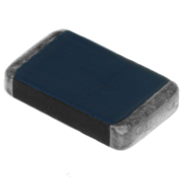
| CRCW0805100RFKEA | General load / pull-down / damping | 100 Ω | 0805 chip | Common footprint; easy sourcing for general-purpose loading. |
| ERJ-6ENF1000V | Minimum-load / bias load | 100 Ω | 0805 chip | Widely referenced series for stable general-purpose loads. |
| RK73H2ATTD1001F | Signal loading / bias network | 1 kΩ | 0805 chip | Common search reference for tighter-tolerance chip resistors. |
| WSL2010R0100FEA | High-current load / low-ohm load | 10 mΩ | 2010 power shunt | Low-ohm part often referenced for power testing/current-heavy loads. |
| LRMAP2512-0R050-F | Medium-current resistive load | 50 mΩ | 2512 power shunt | Bigger footprint spreads heat; common for higher power density. |
| FMP200JR-52-10R | Bleeder / minimum load (through-hole) | 10 Ω | Axial power resistor | Common style for simple loads where PCB heat spreading is limited. |
| RH01010R00FE02 | High-power load / dummy load | 10 Ω | Aluminum-housed class | Referenced for heatsinkable dummy-load setups and power testing. |
| HS50 10R J | Chassis-mount load resistor | 10 Ω | Wirewound / heatsink mount | Common search term for robust, continuous-power resistive loads. |
“Same resistance value” does not guarantee the same power derating, pulse handling, surface temperature, or flame behavior. For alternates, validate temperature rise at worst case and confirm the part won’t overstress nearby components or violate enclosure temperature limits.
.png?x-oss-process=image/auto-orient,1/quality,q_70/format,webp)
Load Resistor Selection Checklist (RFQ-Ready)
Copy/paste this into an RFQ so suppliers respond with comparable options—without hidden thermal assumptions.
| Decision question | Why it affects selection | What to specify in RFQ |
|---|---|---|
| Use case | Defines whether you optimize for heat, precision, or parasitics. | Minimum load / bleeder / LED / termination / dummy load / bias. |
| Operating voltage & current | Sets worst-case dissipation. | Vmax, Imax, duty cycle, load step profile (if applicable). |
| Power & temperature rise limit | Prevents drift, damage, and safety issues. | Continuous P, pulse P, max body temp or max ΔT above ambient. |
| Accuracy needs | Matters if load sets current/thresholds or affects calibration. | Resistance value, tolerance, TCR, long-term drift (if needed). |
| Package & footprint | Determines thermal performance and alternate flexibility. | Exact size (e.g., 0805/1206/2512), mounting, heatsink method. |
| Safety & sourcing | Avoids redesign when supply shifts; avoids unsafe failure modes. | Flame/fusible requirement, lifecycle, lead time, approved alternates plan. |
CTA: Get Load Resistors Matched to Watts + Temperature Rise (Not Just Ohms)
If you’re locking a BOM, building a dummy-load fixture, or replacing an EOL part under supply pressure, send an RFQ with your worst-case voltage/current, duty cycle, ambient temperature, and allowed temperature rise. You’ll get options that protect reliability and avoid “hot part surprises.”
- Resistance value + tolerance/TCR (if functional)
- Vmax, Imax, duty cycle, and any pulse profile
- Ambient temperature range + enclosure/airflow notes
- Allowed resistor surface temperature (or ΔT limit)
- Package/footprint and heatsinking method
FAQ: Load Resistor Selection & Sourcing
What is a load resistor used for?
A load resistor is used to intentionally draw current—such as creating a minimum load for a power supply, discharging capacitors (bleeder), limiting LED current, providing signal termination, or acting as a dummy load for testing. The selection is typically dominated by worst-case power dissipation and safe temperature rise.
How do I calculate the power rating needed for a load resistor?
Compute worst-case dissipation using P = V²/R (if voltage is known) or P = I²R (if current is known). Then apply derating for ambient temperature, enclosure airflow, and PCB heat spreading. If you cannot validate thermally yet, design with significant margin (often 2× for PCB loads; more for enclosed products).
Why does my load resistor run hotter than expected?
Datasheet power ratings assume specific mounting and ambient conditions. On a small PCB with limited copper, temperature rise can be much higher. Nearby hot components, blocked airflow, or enclosure heat trapping can also increase resistor body temperature. Measure actual temperature and redesign for more margin (higher power class, more copper, multiple resistors, or better placement).
Can I substitute a “same-ohms” resistor as a load resistor?
Not safely without checking power rating/derating, pulse handling, temperature rise, and safety behavior (flame/fusible if relevant). Two resistors with the same resistance value can behave very differently thermally, which can change drift, reliability, and nearby component stress.
What should I include in an RFQ for load resistors?
Include use case, resistance value, maximum voltage/current, duty cycle, ambient temperature range, allowed temperature rise or maximum resistor body temperature, package/footprint, and any precision requirements (tolerance/TCR) if the resistor affects current setting or calibration. This makes quotes comparable and avoids thermal surprises.

Related Articles
- ·LED Turn Signal Resistor: How to Size, Mount, Derate & Troubleshoot Hyperflash (Without Melting Anything)
- ·Pull-Up & Pull-Down Resistors: How to Choose Values That Make Digital Inputs Reliable
- ·Load Resistor: How to Choose, Size, and Troubleshoot the “Small Part” That Breaks Big Systems
- ·How to Select Common Input Resistors for a Differential Amplifier (Without Killing CMRR)
- ·How to Choose a Shunt Resistor for Accurate Current Sensing
- ·How to Choose the Right Ballast Resistor (Automotive, LEDs, Inrush & More)
- ·How to Choose the Right Neutral Earthing Resistor (NER) for MV/LV Ground Fault Protection
- ·How to Choose the Right Force Sensitive Resistor (FSR) for Touch, Pressure & Load Detection
- ·Standard Resistor Values (E-Series) — A Field Guide for Real-World Design
- ·Blower Motor Resistor — The Real Reason Your Fan Only Works on “High”








.png?x-oss-process=image/format,webp/resize,h_32)


