
 German
 Japanese
 Portuguese
 Korea
Korea
 Mexico
 Dutch
Dutch


Pull-Up & Pull-Down Resistors: How to Choose Values That Make Digital Inputs Reliable

This is not a “what is a pull-up resistor” encyclopedia page. It’s a decision guide for engineers, buyers, and manufacturing teams who need inputs that boot correctly, buses that don’t hang, and products that survive noise, leakage, and supply substitutions—without mysterious field failures.
.png?x-oss-process=image/auto-orient,1/quality,q_70/format,webp)
One-Screen Answer (Selection + Procurement)
Pull-up and pull-down resistors exist for one job: prevent floating logic states. The selection question is not “do I need one?”—it’s: how strong should the pull be to survive noise, leakage, and speed requirements without wasting power or breaking protocols?
- General MCU input: start at 10 kΩ (good balance of noise vs power).
- Noisy environment / long wire: 4.7 kΩ (stronger pull, better noise immunity).
- Ultra-low power: 47–100 kΩ (only if leakage/noise allow).
- I²C/open-drain: start at 4.7 kΩ (then compute rise-time and sink current).
- Boot straps: follow the datasheet’s recommended range (often 10–100 kΩ), but validate leakage and strap timing.
Using a weak pull (like 100 kΩ) on a long wire or near switching noise. The input becomes an antenna. It may pass in the lab, then fail in the field as spurious interrupts, boot mode changes, or stuck I²C lines.
Speed need: stronger pull helps edges (especially open-drain) but increases current.
Noise/leakage risk: stronger pull wins.
Battery life: weaker pull saves power but requires clean layout and low leakage.
Supply risk: lock the resistor footprint/value family, and document why that value was chosen.
What Pull-Up / Pull-Down Resistors Actually Do (and Why Inputs Float)
A digital input pin is usually a high-impedance node. High impedance is great for power—until it meets real life: EMI, capacitive coupling, leakage currents, human touch, cable harnesses, and ESD structures. Without a defined bias, the input voltage can drift into the undefined region between logic low and logic high.
Connects the node to VDD through a resistor so the default state is logic high. A switch/transistor can pull the node down when active.
Connects the node to GND through a resistor so the default state is logic low. A switch/transistor can pull the node up when active.
Pull resistors are not about “making logic work.” They are about controlling the default state in the presence of real-world noise and leakage. If your product ships, it will see conditions your bench never saw.
.png?x-oss-process=image/auto-orient,1/quality,q_70/format,webp)
Decision Question: How Do You Size Pull-Up / Pull-Down Resistors?
Choosing pull resistor values is a trade between four forces: noise immunity, edge speed (RC), power consumption, and logic margin under leakage. The “right” value depends on what is attached to the node: a mechanical switch, an open-drain bus, a strap pin, or a transistor.
- Determine the required default state: should the node idle HIGH (pull-up) or idle LOW (pull-down)?
- Estimate leakage & bias currents: input leakage, ESD diode leakage, external device leakage, contamination, humidity.
- Set a logic-margin target: ensure worst-case leakage does not move the node into the undefined zone.
- Check speed (RC): node capacitance (pin + trace + cable) and required rise/fall time.
- Check power: when the node is actively pulled against the resistor, compute current and dissipation.
- Validate in the worst environment: long cable, cold start, EMC burst, and brownout scenarios.
If you need a stronger bias, decrease R. If you need lower power, increase R—but only if leakage/noise allow it. For many MCU inputs, 10 kΩ is a sweet spot because it beats typical leakage and is not too power-hungry.
A pull-up that is held low consumes I = V/R. Example: 3.3 V with 4.7 kΩ → about 0.7 mA. Multiply by many lines and your “tiny” pulls become a measurable battery drain.
MCU Digital Inputs: Buttons, Interrupts, and “Ghost Triggers”
The most common pull resistor use is a mechanical button or external signal into a microcontroller. This is also where the most “mystery bugs” happen: false interrupts, random wake-ups, and boot-time glitches. The root cause is almost always a floating or weakly biased input combined with noise and cable capacitance.
- Internal pull-up/down is convenient but varies widely in resistance and tolerance.
- External pull is predictable, more robust to noise, and easier to qualify for production.
- Use internal pulls for short traces and clean environments; use external pulls for cables, EMC, and safety-critical signals.
Debounce is not only firmware. A stronger pull can reduce susceptibility to bounce-induced false edges by making the node less “floaty.” For long wires, consider a pull + small RC filter, but verify that your interrupt edge still meets timing.
.png?x-oss-process=image/auto-orient,1/quality,q_70/format,webp)
Open-Drain Signals & I²C: Pull-Ups Are Not Optional (They Are the Bus)
In open-drain/open-collector systems, devices can pull the line low but cannot drive it high. The pull-up resistor provides the rising edge. That means pull-up selection directly sets rise time, maximum speed, and noise margin.
- Rise time: R with bus capacitance must meet timing (otherwise edges are too slow).
- Sink current: when the line is low, devices must safely sink I = V/R.
Many designs start at 4.7 kΩ for 3.3 V I²C on short buses. Longer traces, more devices, or higher speed may require stronger pull-ups (lower R), but verify sink current and EMI.
- Bus “stuck low”: short, a device holding low, or pull-up too weak to overcome leakage.
- Random NACK / corrupted data: rise time too slow, noise coupling, or pull-up too weak in a noisy environment.
- EMI spikes: pull-up too strong causing sharp edges; add series damping or adjust pull-up value.
Boot Strap Pins: When a Wrong Pull Resistor Bricks Your Board (Softly)
Many MCUs/SoCs read “strap pins” at reset to select boot mode, voltage options, or peripheral mapping. A pull-up/pull-down resistor sets the default. The danger is subtle: the board boots “most of the time,” then fails in manufacturing or after a component substitution.
- The strap is sampled during a short reset window—RC timing matters.
- External circuits attached to the strap pin can fight the pull.
- Leakage through ESD diodes or level shifters can bias the strap unexpectedly.
For strap pins, follow the datasheet range and validate across voltage ramp rates and temperature. Treat any circuit changes on that pin (ESD, connector, level shifter) as a strap re-validation event.
.png?x-oss-process=image/auto-orient,1/quality,q_70/format,webp)
Decision Question: How Noisy Is Your Environment (and How Strong Should the Pull Be)?
Pull resistor selection is a noise problem disguised as a logic problem. Long traces and cables add capacitance and antenna behavior. Nearby switching nodes inject charge through coupling capacitance. A stronger pull reduces the node’s susceptibility by lowering its impedance.
- False interrupts or wakeups
- Inputs change state when you touch the cable
- Failures near motors, relays, or SMPS switching edges
- EMC test triggers unexpected resets
Stronger pulls increase current when the line is asserted against the pull. For buses, too-strong pull-ups can increase EMI and exceed sink-current limits. Strong is good—until it breaks your power budget or device ratings.
Layout Matters: The Pull Resistor Can’t Fix a Bad Return Path
A pull resistor is only as good as the node it biases. If your layout lets switching currents share the same return path, the input reference moves and you get logic glitches. If your input trace runs next to a fast edge, the trace gets injected.
.png?x-oss-process=image/auto-orient,1/quality,q_70/format,webp)
- Place pull resistors close to the MCU pin for short bias loop.
- Keep input traces away from switching nodes (buck SW, MOSFET gates, clocks).
- Use a solid ground reference; avoid routing over splits.
- For cable inputs, consider series resistance and TVS placement strategy.
If a product is assembled in multiple factories or board revisions, your pull choice should tolerate small layout shifts. Stronger pulls and better routing discipline reduce sensitivity to variance.
Troubleshooting Path: Symptoms → Root Causes → Fixes
Pull-up/pull-down issues rarely show up as “the resistor is wrong.” They show up as system behavior: random triggers, stuck buses, boot failures, or power drain. Use this matrix to quickly narrow the cause.
| Symptom | Likely root cause | Fast verification | Fix |
|---|---|---|---|
| False interrupts / wakeups | Input floating or pull too weak; coupling from nearby switching | Scope the pin; touch cable; check noise bursts | Lower R (stronger pull), route away from noise, add RC/Schmitt if needed |
| I²C errors / NACK | Rise time too slow; pull-up too weak; too much bus capacitance | Measure rise time; count devices and cable length | Reduce R, reduce bus C, lower speed, check sink current limit |
| Bus stuck low | Device holding line low; short; leakage overpowering pull-up | Disconnect devices one-by-one; measure static current | Find offender, fix short/leakage, strengthen pull if within sink limits |
| Wrong boot mode | Strap pin leakage/RC; external circuit fighting pull | Check strap level during reset; test different ramp rates | Adjust pull value per datasheet, reduce loading, isolate strap circuitry |
| Unexpected battery drain | Pull held active against resistor; too-strong pulls across many lines | Measure current in sleep and active states | Increase R where safe, change topology, use wake gating or different default logic |
Supply Continuity: Why “Any 10 kΩ” Isn’t Always Equivalent
For pull resistors, value is the headline—but sourcing surprises still happen when tolerance, package, voltage rating, and assembly constraints shift. The safest production plan is to define the pull resistor as part of a known-good input solution, not a generic line item.
- Standardize a small set of pull values (e.g., 4.7 kΩ, 10 kΩ, 47 kΩ) across designs.
- Lock package families that your assembly line handles well.
- For strap pins and buses, treat alternates as a validation event: boot behavior, rise time, EMI, and leakage.
- Document “why this value” in the design notes so substitutions don’t undo the engineering intent.
Common Pull-Up / Pull-Down Starting Points (No Brand Names)
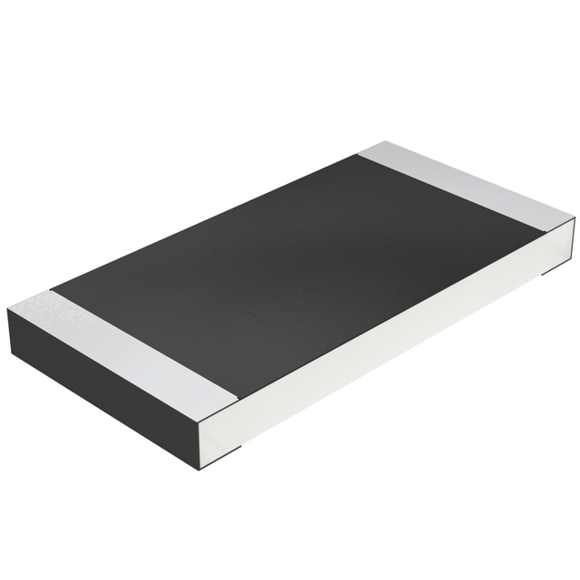
Pull resistors are typically standard values rather than special “part families.” Below are common, widely used starting points. Always confirm with your system constraints: leakage, bus capacitance, required speed, and power budget.
| Use case | Default direction | Common value | Why it’s common | Watch-outs |
|---|---|---|---|---|
| MCU button input (short trace) | Pull-up | 10 kΩ | Balanced noise immunity and power | Cable harness may need stronger pull |
| Long wire / noisy input | Pull-up or pull-down | 4.7 kΩ | Stronger bias against noise | Higher current when asserted |
| Ultra-low-power wake pin | Usually pull-up | 47–100 kΩ | Minimizes current | More sensitive to leakage and EMI |
| I²C SDA/SCL (typical) | Pull-up | 4.7 kΩ | Common starting point | Verify rise time & sink current |
| Boot strap pins | Per datasheet | 10–100 kΩ | Minimizes loading while defining state | Validate ramp rate, leakage, reset window |
Pull resistor selection is system-specific. A value that works on a short PCB trace may fail on a harness. If you must substitute, re-check: leakage margin, rise time (for open-drain), and power.
.png?x-oss-process=image/auto-orient,1/quality,q_70/format,webp)
Pull-Up / Pull-Down Selection Checklist (RFQ-Ready)
Copy/paste this into an RFQ so suppliers respond with comparable options—without hidden assumptions.
| Decision question | Why it affects selection | What to specify in RFQ |
|---|---|---|
| Use case | Determines pull strength, power, and timing | Button input / strap / open-drain bus / connector input |
| Voltage & default state | Sets current and logic direction | VDD level, pull-up or pull-down requirement |
| Noise / cable length | Controls required bias strength | Harness length, EMI environment, proximity to switching nodes |
| Timing / speed | RC affects edge rates (critical for open-drain) | Bus speed, rise-time target, node capacitance estimate |
| Power budget | Pull current accumulates across many lines | Max acceptable current when asserted, sleep budget |
| Package & sourcing | Prevents “same value, different assembly outcome” | Package size, tolerance, lifecycle/alternates plan |
CTA: Get Pull Resistors Matched to Noise + Speed + Power (Not Just “10 kΩ”)
If you’re debugging random triggers, qualifying an alternate, or building an I²C bus that must pass EMC and production, send an RFQ with your node type, bus speed, cable length, and power budget. You’ll receive options that protect your schedule and reduce re-test risk.
- Use case: MCU input / strap / open-drain bus / connector
- VDD and required default state
- Bus speed (if open-drain) and estimated capacitance
- Noise environment and cable length
- Power/sleep current budget
FAQ: Pull-Up / Pull-Down Resistors
Pull-up vs pull-down: which one should I use?
Use a pull-up when the safe/default state should be logic HIGH (and the active element pulls low). Use a pull-down when the safe/default state should be logic LOW (and the active element pulls high). For open-drain buses like I²C, pull-ups are mandatory because devices do not drive high.
What value should I start with for an MCU input?
Start with 10 kΩ for short, clean PCB traces. If the input is on a cable, near switching noise, or fails EMC, move toward 4.7 kΩ. If you must minimize power, consider 47–100 kΩ but validate leakage and noise margin.
Why does my input trigger randomly?
Random triggers usually mean the input is floating or weakly biased, so it picks up noise through coupling or cable antenna effects. Strengthen the pull, improve routing/return path, and consider adding RC filtering or a Schmitt-trigger input when needed.
How do pull-up resistors affect I²C speed?
The pull-up resistor and bus capacitance set the rise time. If the pull-up is too weak (too large R), edges rise too slowly and the bus fails at higher speeds. If the pull-up is too strong (too small R), devices must sink more current and EMI can increase.
Can I replace a pull resistor with a different value during shortages?
Yes, but treat it as a design change: re-check logic margin under leakage, power consumption when asserted, and rise time for open-drain lines. Validate cold start/boot strap behavior and perform a quick EMC smoke test if the node connects to a cable or noisy environment.

Related Articles
- ·LED Turn Signal Resistor: How to Size, Mount, Derate & Troubleshoot Hyperflash (Without Melting Anything)
- ·Pull-Up & Pull-Down Resistors: How to Choose Values That Make Digital Inputs Reliable
- ·Load Resistor: How to Choose, Size, and Troubleshoot the “Small Part” That Breaks Big Systems
- ·How to Select Common Input Resistors for a Differential Amplifier (Without Killing CMRR)
- ·How to Choose a Shunt Resistor for Accurate Current Sensing
- ·How to Choose the Right Ballast Resistor (Automotive, LEDs, Inrush & More)
- ·How to Choose the Right Neutral Earthing Resistor (NER) for MV/LV Ground Fault Protection
- ·How to Choose the Right Force Sensitive Resistor (FSR) for Touch, Pressure & Load Detection
- ·Standard Resistor Values (E-Series) — A Field Guide for Real-World Design
- ·Blower Motor Resistor — The Real Reason Your Fan Only Works on “High”





.png?x-oss-process=image/format,webp/resize,h_32)


