
 German
 Japanese
 Portuguese
 Korea
Korea
 Mexico
 Dutch
Dutch


Ultrasound Electronics: Tx/Rx, TGC, Beamforming & Compliance
August 15 2025 
From pulsers to pixels. Our goal: clean echoes, crisp images, quiet EMC, and happy test labs.
From pulsers to pixels. Our goal: clean echoes, crisp images, quiet EMC, and happy test labs.
.png?x-oss-process=image/auto-orient,1/quality,q_70/format,webp)
1) System overview & signal chain
High-level flow: probe array → T/R protection → low-noise receive chain with TGC → high-speed ADCs → FPGA/SoC beamforming → CPU/GPU image processing & UI. A medical-grade power tree and isolation strategy keep patient and mains worlds politely apart.
2) Probe hardware (PZT/CMUT), cabling & T/R protection
- Transducers: PZT ceramic stacks dominate; CMUT-on-CMOS appears in some designs. Choose frequency/aperture per application (e.g., cardiac vs abdominal).
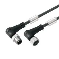
- Cabling: multi-coax or micro-coax bundles with braided/shielded grounds; strain relief and EMI ferrites near connectors.
- T/R protection: diode clamps, limiter modules, or MOSFET-based T/R switches to protect the LNA from HV transmit bursts.
- Probe ID: EEPROM/1-Wire or NFC for auto-configuration, calibration, and usage logs.
.png?x-oss-process=image/auto-orient,1/quality,q_70/format,webp)
3) Transmit path: HV pulsers & beamforming timing
- HV pulsers: controlled edges to minimize transducer stress and cable radiation; support bipolar/tri-level drive when needed.
- Beamformer timing: per-element delays (ps–ns scale) create focus/steer angles; skew matching across channels is critical.
- Protection: blanking windows to decouple Rx chain during Tx; use snubbers and proper return paths for HV energy.
.png?x-oss-process=image/auto-orient,1/quality,q_70/format,webp)
4) Receive path: LNA, TGC, filters & ADC
Echoes arrive weak and frequency-dependent—the Rx path must be quiet, linear, and adjustable over depth.
.png?x-oss-process=image/auto-orient,1/quality,q_70/format,webp)
- LNA/VGA: chopper or low 1/f op-amps; programmable gain over large range to maintain SNR across depth.
- Filters: selectable high-pass/low-pass to match transducer band; anti-aliasing before ADC.
- ADCs: multi-channel, high-speed (tens of MSPS class depending on modality); deterministic sampling alignment across channels.
5) Digital beamforming architectures
- DAS (delay-and-sum) on FPGA/SoC: parallel delay lines + apodization + accumulation; heavy on memory bandwidth.
- Plane-wave / synthetic aperture: fewer firings, more processing; good for ultrafast imaging and elastography.
- Hybrid: analog sub-array beamforming in probe + digital beamforming in system to reduce cable count.
.png?x-oss-process=image/auto-orient,1/quality,q_70/format,webp)
6) Imaging modes & data paths
- B-mode: envelope detection → log compression → scan conversion → display.
- M-mode: single line vs time; low data rate, timing accuracy matters.
- Doppler: color/power Doppler maps; PW Doppler spectrogram; requires stable PRF, wall filters, and FFT pipelines.
- Harmonic imaging: transmit fundamental, receive harmonic band; improves contrast, needs proper filtering.
- Elastography: shear-wave or strain methods; high frame rate and precise timing.
.png?x-oss-process=image/auto-orient,1/quality,q_70/format,webp)
7) Clocks, jitter & sync
- Master clock tree: low-jitter PLLs; distribution with matched length; per-ADC clock skew budgeted.
- Triggers: deterministic sync between Tx fire and Rx sampling; timestamping for multi-probe/3D.
.png?x-oss-process=image/auto-orient,1/quality,q_70/format,webp)
8) Power, isolation & patient safety
.png?x-oss-process=image/auto-orient,1/quality,q_70/format,webp)
- Use isolated DC-DC for probe/Rx domains; digital isolators on data/control lines.
- Respect creepage/clearance per PCB stackup; verify patient leakage limits (BF/CF strategy per architecture).
- Grounding/bonding plan: chassis, shield, and signal returns defined to avoid loops.
9) Thermal & acoustic output considerations
- Thermals: spreader plates, heat pipes or quiet fans; keep Rx AFEs cool to reduce drift/noise.
- Acoustic output: monitor and control system output indices (e.g., mechanical/thermal indices per your modality and region) and implement limits/alerts within the supervisory firmware.
10) PCB layout & EMC practices
- Separate HV Tx planes from low-level Rx; keep return currents short and predictable.
- Cable entry filtering: common-mode chokes, RC, TVS; shield termination at chassis with controlled impedance.
- Suppress ringing on pulsers; contain dV/dt; use guard traces on sensitive nodes.
.png?x-oss-process=image/auto-orient,1/quality,q_70/format,webp)
11) Compliance mapping (IEC/ISO)
| Topic | Standard | Engineering artifact |
|---|---|---|
| Basic safety | IEC 60601-1 | schematics, creepage/clearance, leakage tests |
| EMC | IEC 60601-1-2 | filter/shield plans, test matrix & results |
| Diagnostic ultrasound | IEC 60601-2-37 | output controls/limits, labeling, performance tests |
| Software lifecycle | IEC 62304 | software safety class, verification evidence |
| Usability | IEC 62366 | use-related risk files, formative/summative reports |
| Risk management | ISO 14971 | hazard analysis, FMEA/FMEDA, risk controls |
| QMS | ISO 13485 | DHF/DMR, traceability, change control |
12) Risk analysis (hazards → mitigations)
| Hazard | Cause | Mitigation |
|---|---|---|
| LNA damage | insufficient Tx/Rx isolation | limiters, T/R switch blanking, validated protection network |
| Image artifacts | clock skew, jitter, EMI | low-jitter clocks, matched routing, shielding, timing self-test |
| Over-output | control bug or misconfig | firmware limits, watchdog, output monitor, calibration interlocks |
| Excessive leakage | isolation fault | insulation monitoring, test at production/service, robust barriers |
| Data loss | power fail mid-write | journaling/transactional writes, supervisors, hold-up energy |
13) Sample BOM highlights
| Function | Component class | Selection cues |
|---|---|---|
| Tx drivers | HV pulsers/beamformer ICs | edge control, voltage rating, channel density |
| T/R protection | limiters, MOSFET switches | clamp level, insertion loss, recovery time |
| Rx AFE | LNA, VGA/TGC, anti-alias filters | noise density, gain steps, bandwidth |
| Digitization | multi-channel high-speed ADCs | SNR/ENOB, sync features, power |
| Processing | FPGA/SoC FPGA + DDR | logic cells, DSP blocks, memory BW |
| Power | isolated DC-DC, PMICs | isolation rating, ripple, thermal |
| Isolation | digital isolators | BW/latency, CMTI, creepage |
| Clocking | PLLs/clock trees | jitter, skew control, fan-out |
| Storage | eMMC/SSD, FRAM | throughput, endurance, power-fail safety |
| Connectivity | GbE/USB/Wi-Fi | bandwidth, EMC, isolation strategy |
14) Manufacturing QA, calibration & service
- ICT/FCT: channel gain/phase match; clock skew check; Tx blanking timing; ADC linearity.
- Calibration: TGC curve verification, probe ID mapping, timing skew trims stored to NVM.
- Image QA: phantom tests (resolution/contrast), Doppler PRF/velocity checks, logging of acceptance results.
- Service: fan/filter access, probe cycle count, isolation/leakage retest at intervals.
15) Related guides
- Read the full Endoscopic Imaging electronics guide
- Read the full X-ray & CT electronics guide
- Read the full Patient Monitoring System electronics guide
Need HV pulsers, AFEs, ADCs or FPGA options? Talk to Ersa.

Related Articles
Popular Posts


.png?x-oss-process=image/format,webp/resize,h_32)


