

STMicroelectronics
STF40N65M2
Single FETs, MOSFETs

Not available to buy online? Want the lower wholesale price? Please Send RFQ to get best price, we will respond immediately


.png?x-oss-process=image/format,webp/resize,p_30)


STF40N65M2 Description
STF40N65M2 Description
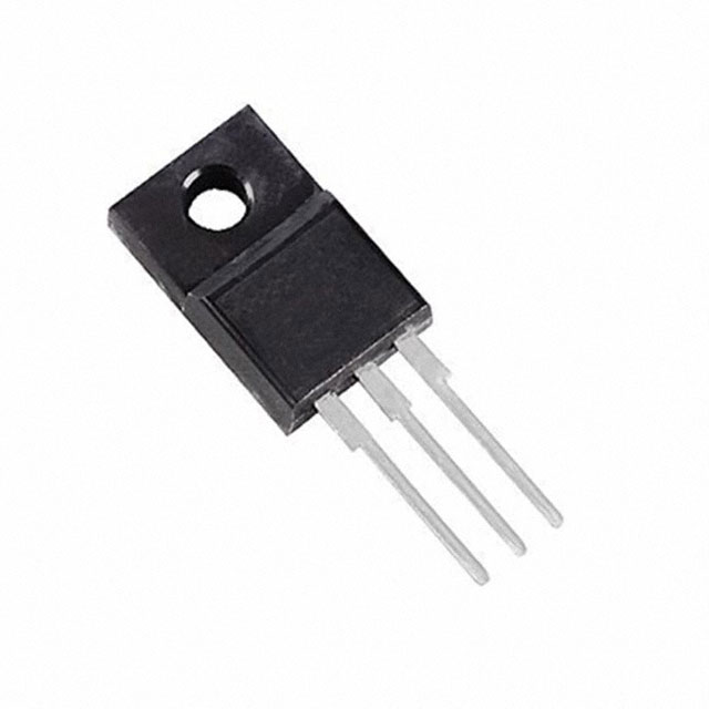
The STF40N65M2 from STMicroelectronics is a high-performance N-channel MOSFET designed for demanding power applications. Built using ST's advanced MDmesh™ M2 technology, it delivers an optimal balance of low on-resistance (99mΩ @ 16A, 10V) and high switching efficiency, making it ideal for high-voltage, high-current environments. With a 650V drain-to-source voltage (Vdss) and a continuous drain current (Id) of 32A (Tc), this MOSFET is engineered to handle significant power loads while maintaining thermal stability up to 150°C (TJ). Packaged in a TO220FP through-hole format, it ensures robust mechanical and thermal performance in industrial and automotive applications.
STF40N65M2 Features
- Low On-Resistance: 99mΩ @ 16A, 10V minimizes conduction losses, improving efficiency.
- High Voltage Rating: 650V Vdss ensures reliability in high-power circuits.
- Fast Switching: Gate charge (Qg) of 56.5nC @ 10V and low input capacitance (2355pF @ 100V) enhance switching speed.
- Thermal Robustness: 25W power dissipation (Tc) and a wide operating temperature range (-55°C to 150°C) suit harsh environments.
- Reliability: ROHS3 compliant, REACH unaffected, and MSL 1 (unlimited) for long-term durability.
- Drive Flexibility: Vgs(max) of ±25V and a threshold voltage (Vgs(th)) of 4V @ 250µA ensure compatibility with various gate drivers.
STF40N65M2 Applications
- Switched-Mode Power Supplies (SMPS): High efficiency and low losses make it ideal for AC/DC converters.
- Motor Drives: Robust performance supports inverter and motor control systems.
- Industrial Power Systems: Suitable for welding equipment, UPS, and solar inverters.
- Automotive Electronics: Used in electric vehicle (EV) charging and DC-DC converters.
- Lighting: Efficiently drives high-power LED drivers and ballasts.
Conclusion of STF40N65M2
The STF40N65M2 stands out as a high-efficiency, high-reliability MOSFET for power electronics. Its MDmesh™ M2 technology ensures superior switching performance and thermal management, while its 650V rating and 32A current capability make it versatile for industrial, automotive, and energy applications. With low Rds(on), fast switching, and robust packaging, it is an excellent choice for designers seeking to optimize power density and system reliability.
Tech Specifications
STF40N65M2 Documents
Download datasheets and manufacturer documentation for STF40N65M2
Mult Dev Wafer Site Add 3/Aug/2018 STF40N65M2 STF40N65M2 Related Parts


Shopping Guide


.png?x-oss-process=image/format,webp/resize,h_32)


©2025 ERSA Electronics Corporation.