
 German
 Japanese
 Portuguese
 Korea
Korea
 Mexico
 Dutch
Dutch


Texas Instruments
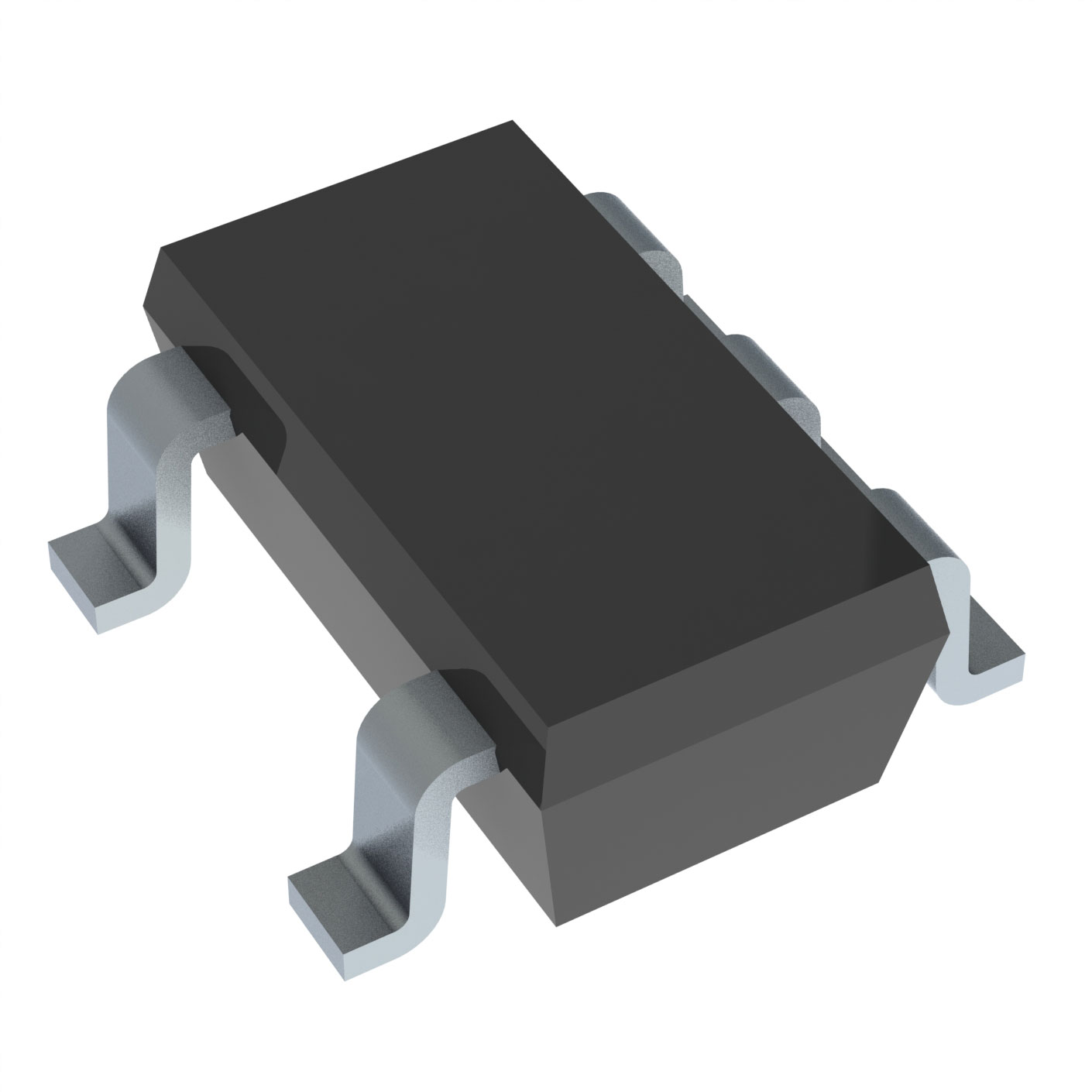
SN74AUP1G34DBVR

Why Choose Us?
Professional Platform
B2B & B2C purchasingDelivery at full speed
1-2 days deliveryWide variety
Original manufacturers365 days guarantee
Responsible quality
.png)


Tech Specifications
SN74AUP1G34DBVR Description
The SN74AUP1G34DBVR is a single-pole, double-throw (SPDT) analog switch manufactured by Texas Instruments. It is a part of the 74AUP1Gxx series of analog switches that are designed for low-power and low-voltage applications.
Description:
The SN74AUP1G34DBVR is a digital-controlled analog switch that can handle a wide range of input signals. It is available in a small SOT-23 package, making it suitable for space-constrained applications. The switch has a single input and two outputs, allowing it to route an input signal to either of the two outputs based on the control signal.
Features:
- Low power consumption: The SN74AUP1G34DBVR operates on a low supply voltage of 1.65V to 5.5V and has a low power consumption of 1.1µA per channel.
- High bandwidth: The switch has a high bandwidth of -3dB at 170MHz, making it suitable for high-speed signal routing applications.
- Low distortion: The SN74AUP1G34DBVR has a low distortion of -70dBc, ensuring that the signal quality is maintained when switching between inputs and outputs.
- Wide input voltage range: The switch can handle input signals with a voltage range of -0.5V to 5.5V, making it suitable for a wide range of applications.
- Short-circuit protection: The SN74AUP1G34DBVR has built-in short-circuit protection to prevent damage to the device in case of a short circuit.
Applications:
The SN74AUP1G34DBVR has a wide range of applications due to its low power consumption, high bandwidth, and low distortion. Some of the potential applications include:
- Audio switching: The switch can be used to route audio signals in audio systems, such as in headphones or speakers.
- Medical equipment: The low power consumption and high bandwidth make the SN74AUP1G34DBVR suitable for use in medical equipment, such as ultrasound machines or patient monitoring systems.
- Industrial control systems: The switch can be used to route signals in industrial control systems, such as in motor control or sensor applications.
- Data acquisition systems: The SN74AUP1G34DBVR can be used to switch between different data sources in data acquisition systems.
- Wireless communication systems: The switch can be used to route signals in wireless communication systems, such as in RF front-ends or antenna switching applications.
In summary, the SN74AUP1G34DBVR is a versatile analog switch that offers low power consumption, high bandwidth, and low distortion, making it suitable for a wide range of applications, including audio switching, medical equipment, industrial control systems, data acquisition systems, and wireless communication systems.
FAQ
| Quantity | Unit Price | Ext. Price |
|---|---|---|
| 1+ | $0.26400 | $0.26 |
| 10+ | $0.18216 | $1.82 |
| 25+ | $0.16157 | $4.04 |
| 100+ | $0.13895 | $13.89 |
| 250+ | $0.12813 | $32.03 |
Not available to buy online? Want the lower wholesale price? Please Send RFQ to get best price, we will respond immediately


.png?x-oss-process=image/format,webp/resize,h_32)


