
 German
 Japanese
 Portuguese
 Korea
Korea
 Mexico
 Dutch
Dutch


Common Mode Choke — The Tiny “Noise Bouncer” Your Board Deserves

If your board’s EMI plot looks like a city skyline from a superhero movie, a common mode choke is the bouncer that guards the door. This deep-dive explains how a common mode choke works, where to place it, how to read the curves, how to keep eye diagrams alive, and how to pass compliance without summoning an angry test lab.
Answer Box — TL;DR
- A common mode choke presents high impedance to common-mode noise while keeping differential signals mostly intact. Two windings on one core are magnetically coupled to cancel differential flux.
- Place the common mode choke close to the noisy/long I/O (USB, HDMI/DP, Ethernet, CAN/LIN, DC input) and as near as possible to the connector or source of emissions. Keep stubs under ~1 mm for high-speed pairs.
- Key specs: LCM (common-mode inductance), ZCM(f) @ 100 MHz, leakage LLK, rated current & DCR, SRF, and insertion-loss curves for both CM and DM paths.
- For high-speed pairs, choose a common mode choke with low DM insertion loss and flat return loss across the band; verify with S-parameters and eye diagrams.
- Automotive? Look for AEC-Q200 qualification and wide temperature rating; mount before ESD arrays or after, depending on the strategy (see section 7).
1) What Is a Common Mode Choke? (Plain English, No Wizardry)
A common mode choke is a two-(or more) winding inductor on a shared magnetic core. The windings are arranged so that differential currents (the signal you want) flow in opposite directions and cancel flux, while common-mode noise currents (the junk you don’t want) add flux and see a big inductive impedance. Think of the common mode choke as a VIP rope: friends with opposite wristbands stroll through; a crowd with the same wristband hits a wall.
Why do you need a common mode choke? Because cables, long traces, and ground bounce happily radiate common-mode noise into the world, especially when your board hosts fast edges, switching supplies, or long differential pairs. Regulatory limits (CISPR 32/25, FCC Part 15) don’t care that your waveform is “beautiful”; they only care about what leaks out.
2) How a Common Mode Choke Works — Magnetic Math Without Tears
Two windings, same core. Let the currents in the pair be +i and −i for differential signaling. The net magnetizing flux from differential currents nearly cancels: ΦDM ≈ N·(i) − N·(i) = 0. For common-mode noise, both conductors carry +icm: ΦCM ≈ N·icm + N·icm = 2N·icm. Result: the common mode choke presents high impedance to CM noise and low impedance to DM signals.
Real life isn’t perfect: leakage inductance (LLK) exists because coupling is not 100%. LLK acts on the DM path and can distort high-speed edges or narrow eye openings if too large. Meanwhile, the CM impedance ZCM(f) rises with frequency up to the self-resonant frequency (SRF), then falls.
| Quantity | Ideal | Reality | Why it matters |
|---|---|---|---|
| CM Impedance ZCM(f) | Large, monotonic ↑ | Peaks near SRF, then ↓ | Know where your noise band is |
| DM Impedance ZDM(f) | Near 0 | Finite from LLK & parasitics | Impacts eye diagram / IL |
| Core Material | N/A | NiZn vs MnZn, permeability vs loss | Sets HF performance & heat |
| Rated Current | Infinite | Saturation & temperature rise | Choose margin for worst case |
Key takeaway: A common mode choke is a filter with two promises: block CM noise and don’t break DM signals. Your job is to pick the part where both promises hold across your band of interest.
.png?x-oss-process=image/auto-orient,1/quality,q_70/format,webp)
3) Where to Use a Common Mode Choke: USB/HDMI/Ethernet/CAN/AC-DC
- USB 2.0/3.x/4: suppress cable-borne CM noise; keep DM insertion loss low. Place the common mode choke close to the connector.
- HDMI/DisplayPort: multiple high-speed lanes with tight eye budgets; choose ultra-low LLK common mode choke or skip if channel loss is tight—validate with S-parameters.
- Ethernet (100/1000BASE-T/2.5G+): CM choke sometimes integrated in magnetics; discrete common mode choke can help at the PHY side if emissions bite.
- Automotive CAN/LIN/FlexRay: rugged CM filtering for long harnesses; AEC-Q200 common mode choke with proper current & temp rating.
- DC-Input lines (SMPS): common mode choke on the input pair reduces conducted emissions up the cable (often paired with X/Y capacitors).
- Audio/IoT: on long unshielded cables to tame touchy EMC issues, especially with Class-D amps and BLE/Wi-Fi coexistence.
Rule: If a cable leaves your enclosure or a long pair travels across boards, ask yourself whether a common mode choke near that boundary could save you a re-spin.
4) Selection Guide: Parameters That Actually Matter
- LCM & ZCM(f): Match the CM impedance peak to your trouble band. For USB2, 100–300 MHz is classic; for USB3/HDMI, check up to several GHz and avoid DM harm.
- Leakage Inductance LLK: Smaller is kinder to DM signals. For fast interfaces, look for “ultra-low leakage” common mode choke series.
- Rated Current & DCR: Ensure temperature rise stays within limits; high DCR wastes budget and heats the choke.
- SRF: Your noise band should sit comfortably below SRF for effective attenuation.
- Package & Footprint: 0805/1206 for signal lines; larger for power lines. Footprint must match differential pair geometry to avoid stubs.
- Environment: AEC-Q200 for automotive; wide temp range (e.g., −40 °C to 125 °C); humidity robustness if near vents.
- Datasheet Curves: Look for CM/DM insertion loss plots, impedance vs frequency, and eye-diagram examples if available.
| Interface | What to optimize | Typical notes |
|---|---|---|
| USB 2.0 (HS) | Moderate ZCM, low LLK | Keep skew minimal; place at connector |
| USB 3.x/4 | Very low DM IL, minimal LLK | Sometimes omit CMC—validate channel |
| HDMI/DP | Ultra-low LLK | CMC after ESD or before? Test both ways |
| Ethernet | CM attenuation near 30–200 MHz | PHY side; watch for added return loss |
| CAN/LIN | Robust ZCM, AEC-Q200 | Protects against harness-borne noise |
| DC-IN | High current rating, ZCM in kHz–MHz | Pair with X/Y caps; check thermal rise |
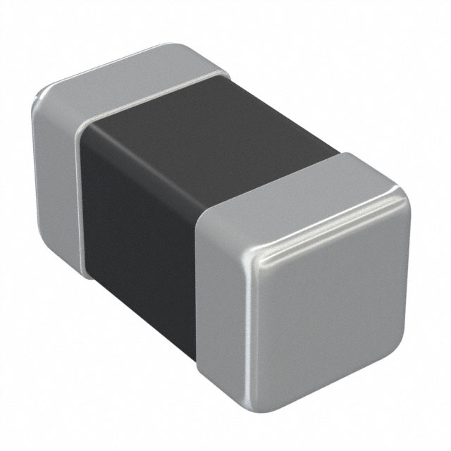
.png?x-oss-process=image/auto-orient,1/quality,q_70/format,webp)
5) PCB Layout & Placement Rules (With Do/Don’t Tables)
- Put the common mode choke first in line near the connector to stop noise at the boundary. For power entry, put the common mode choke before the cable harness.
- Minimize stubs: route symmetrically through the common mode choke footprint; avoid test pads right on the pair; if needed, use inline probe pads.
- Keep pair geometry through the common mode choke: same spacing before/after to maintain differential impedance.
- ESD arrays: often outside the choke (connector-side) to shunt energy before the choke; sometimes inside for eye preservation; test both in high-speed designs.
- Return paths: uninterrupted reference plane; avoid splits/slots under the choke and the pair.
- Thermal: common mode choke can warm up with DC current; don’t cuddle it next to plastic connectors without airflow.
| Do | Don’t |
|---|---|
| Place CMC within ~5–10 mm of connector pins | Route long meanders before CMC |
| Match pair length through package | Stagger vias; avoid asymmetry |
| Short ESD traces; low-cap arrays | High-cap ESD that collapses eye |
| Solid ground under pair & CMC | Plane cuts/slots below CMC |
6) Verify Like a Pro: S-Parameters, Eye Diagrams & EMI Scans
- Extract S-parameters for the common mode choke + pair channel. Inspect IL/return loss for DM and CM. Watch Sdd21 (DM insertion loss) and Scc21 (CM).
- Eye diagrams: simulate or scope with a compliance pattern. The right common mode choke won’t squeeze the eye or add significant jitter.
- Conducted EMI: pre-scan 150 kHz–30 MHz (or automotive bands) with/without the common mode choke to quantify dB improvement.
- Radiated EMI: run near-field probes around the connector & cable; a good common mode choke will drop the hot spots.
- Thermals: log temp rise at worst-case current and ambient; stay within derating curves.
Pro tip: The best common mode choke is the one you can prove doesn’t break your signal while it tames EMI. Numbers or it didn’t happen.
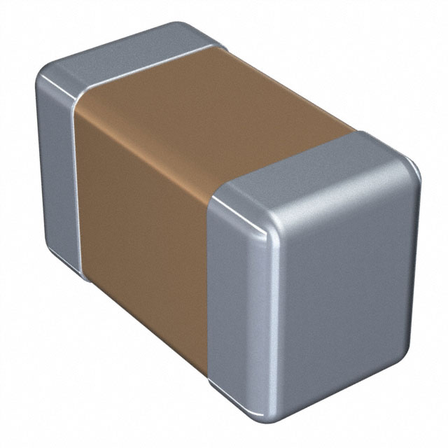
.png?x-oss-process=image/auto-orient,1/quality,q_70/format,webp)
7) Design Recipes: USB 2.0/3.x, HDMI/DP, Ethernet, CAN/LIN, DC-IN
USB 2.0 (480 Mb/s)
- Pick a common mode choke with ZCM peak around 100–300 MHz and low LLK.
- Place within 5 mm of the Type-A/C connector; ESD array connector-side with <0.2 pF per line if possible.
- Verify eye; Sdd21 degradation should be minimal (<1 dB in-band is a good target).
USB 3.x/4 (5–20 Gb/s per lane)
- Only use an ultra-low-leakage common mode choke designed for multi-Gb/s links, or omit entirely if channel budget is tight.
- Channel sim is mandatory; measure with VNA + TDR; avoid any discontinuity beyond what your budget allows.
HDMI/DisplayPort
- Evaluate lane by lane. If a common mode choke is needed for emissions, pick parts with published high-speed S-param data and demo eye plots.
- ESD placement experiment: many teams go connector-side ESD → CMC → SoC; others SoC-side ESD to protect silicon. Choose based on eye impact and ESD target levels.
Ethernet (100/1000BASE-T)
- Magnetics modules already provide CM suppression; an additional board-side common mode choke can help tame stubborn emissions or immunity issues.
- Check return loss and NEXT performance; don’t disturb the PHY’s analog front end.
CAN / LIN / FlexRay (Automotive)
- Use AEC-Q200 qualified common mode choke. ZCM focused below a few tens of MHz is often effective with long harnesses.
- Combine with TVS diodes (low capacitance) and proper termination; route symmetrically.
DC-Input (SMPS)
- Choose high-current common mode choke with low DCR and appropriate core for your switching frequency harmonics.
- Pair with X/Y caps and a differential choke if DM noise dominates; verify compliance margins.
8) Troubleshooting Matrix: Symptom → Observable → Fix
| Symptom | Observable | Likely Cause | Fix |
|---|---|---|---|
| Fails radiated EMI near 200–400 MHz | Cable probe shows CM hot spot | Insufficient CM impedance; poor placement | Add/upgrade common mode choke; move closer to connector; seal plane gaps |
| High-speed eye collapse | Increased DM IL; TDR discontinuity | LLK too large; package parasitics | Pick ultra-low-leakage common mode choke or remove; retune channel |
| Connector warms up | Temp rise at common mode choke pads | Overcurrent; DCR too high | Choose lower DCR choke; check current margin & airflow |
| USB2 random disconnects | Eye height/width marginal | Excess DM attenuation or skew | Shorten stubs; symmetric routing; lower LLK choke |
| CAN bus EMI during crank | Harness CM spikes | Choke saturating; ESD clamp late | AEC-Q200 choke with higher current & better core; move TVS connector-side |
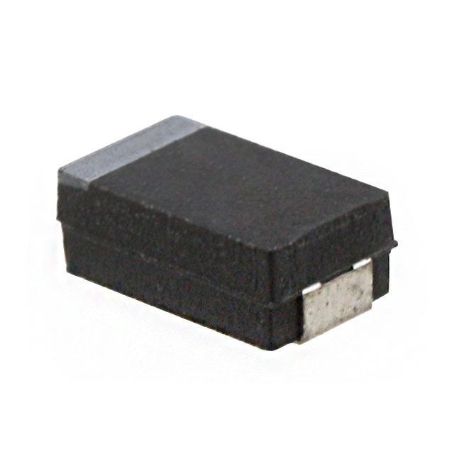
.png?x-oss-process=image/auto-orient,1/quality,q_70/format,webp)
9) Beads, RC & Shields: When a Common Mode Choke Isn’t the Only Answer
- Ferrite beads: good for DM or single-ended lines; can complement a common mode choke on power rails.
- RC snubbers/damping: kill ringing at specific nodes; not a substitute for cable-borne CM noise but helpful locally.
- Shielding & gaskets: enclosure fixes that nuke near-field leaks; pair with a common mode choke for stubborn emissions.
- Grounding strategy: poor bonding between shields/grounds creates CM sources; fix the return path and the common mode choke has less to do.
10) BOM & Reliability: AEC-Q200, Core Materials, Current & Heat
For automotive or industrial, choose an AEC-Q200 qualified common mode choke with the right temperature range and mechanical robustness. NiZn ferrites tend to favor higher-frequency CM impedance; MnZn can offer different trade-offs at lower frequencies. Always check derating: DC bias reduces effective inductance; heat cycles shift performance.
- Current margin: at least 1.5–2× typical line current, more if ambient is hot.
- DCR: lower is better for power and temperature rise—but balance size & cost.
- Potting/encapsulation: may help in harsh environments; confirm thermal path.
- Second source: keep footprints generic and values standard; don’t lock into exotic packages unless necessary.
11) Common Mode Choke FAQ
Does a common mode choke affect my differential signal?
Ideally very little. In practice, leakage inductance and parasitics add some DM insertion loss. Choose a common mode choke with low LLK and verify with S-parameters.
Where should I place ESD relative to the common mode choke?
Often connector-side ESD then the choke, so surge energy is shunted before the choke. For high-speed eyes, try both orders in prototypes and measure.
Is one common mode choke enough for all lanes?
No. Each differential pair usually gets its own common mode choke. Multi-line parts exist but validate crosstalk and symmetry.
Do I need a common mode choke on USB 3.x/HDMI?
Only if emissions require it and the chosen part preserves eye height/width. Sometimes the best choice is no common mode choke plus strong layout and shielding.
How do I know my common mode choke is saturating?
Look for rising distortion or temperature with current, or reduced CM attenuation under load. Check current ratings and core characteristics.
Send interface type, data rate, cable length, and failing frequency bands. We’ll propose 2–3 common mode choke options with layout notes and risk flags.

 FAQ
FAQ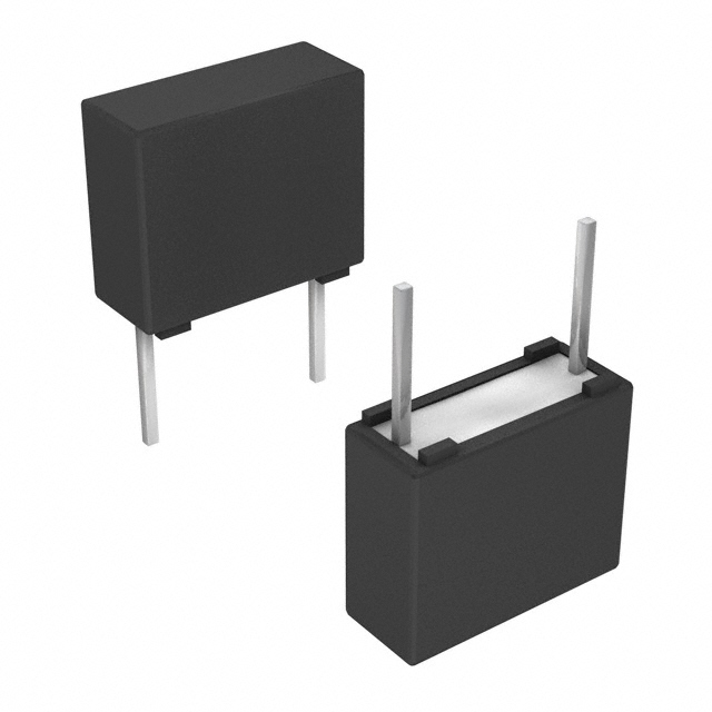


.png?x-oss-process=image/format,webp/resize,h_32)


