
 German
 Japanese
 Portuguese
 Korea
Korea
 Mexico
 Dutch
Dutch


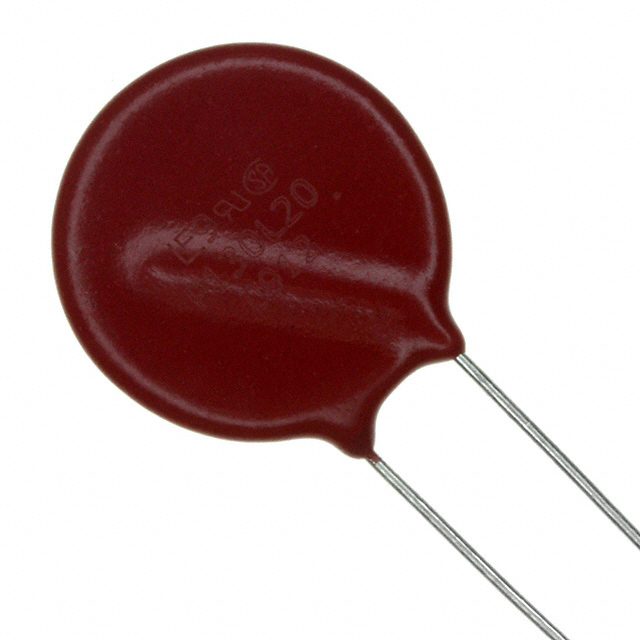
680µH Common Mode Choke — The “Noise Bouncer” With Real-World Superpowers

If your EMI plot looks like a neon skyline from a superhero trailer, a 680µH common mode choke is the doorman that lets good signals in and throws noisy freeloaders out. This guide explains how a 680uh common mode choke works, where it shines, how to select one, how to lay it out, and how to verify it with S-parameters and eye diagrams.
Answer Box — TL;DR
- A 680uh common mode choke gives high impedance to common-mode noise while leaving differential signals mostly untouched; think “block the crowd, wave the pair through.”
- Place the 680uh common mode choke close to the connector or boundary (USB/HDMI/Ethernet/CAN/DC-IN). Keep stubs tiny for high-speed lanes.
- Pick by LCM, ZCM(f), leakage LLK, SRF, DCR, and current rating. Verify with S-parameters (Sdd21/Scc21) and an eye diagram.
- Automotive? Choose AEC-Q200; mind temperature rise and DC bias. For ultra-tight channels, evaluate whether the best CMC is actually none.
1) What is a 680µH Common Mode Choke?
A 680uh common mode choke is a two-winding inductor on one core. Differential currents (+i and −i) cancel flux, so DM signals pass. Common-mode noise currents (+icm and +icm) add flux, so noise sees big impedance. In short: a 680uh common mode choke is a selective bouncer—VIPs (differential pairs) in, rowdy noise out.
Why the specific value, 680 µH? In cable-borne emissions and low-to-mid radio bands, a 680uh common mode choke produces substantial impedance without excessive DM insertion loss, especially for USB 2.0, CAN/LIN and DC-IN lines. The exact sweet spot depends on core material, leakage, and SRF.
2) How a 680uh Common Mode Choke Works (Plain English + Math)
Two windings, same core. For the wanted signal, magnetic fields cancel: ΦDM ≈ N·i − N·i ≈ 0. For common-mode noise they add: ΦCM ≈ N·icm + N·icm = 2N·icm. The 680uh common mode choke therefore looks like a large inductor to CM noise and a small inductor to DM signals.
Reality check: leakage inductance LLK and parasitics exist. LLK acts on the DM path and can shrink eye height if too large. Self-resonant frequency (SRF) sets where ZCM peaks and then falls.
.png?x-oss-process=image/auto-orient,1/quality,q_70/format,webp)
3) Where to Use a 680uh Common Mode Choke
- USB 2.0: classic win for a 680uh common mode choke with ZCM peaking in the 100–300 MHz band.
- USB 3.x/HDMI/DP: channel budgets are tight. Use ultra-low-leakage parts—or omit CMC and rely on layout and ESD selection.
- Ethernet: magnetics provide CM suppression; a board-side 680uh common mode choke may help for nasty cases.
- CAN/LIN (Automotive): a 680uh common mode choke tames harness-borne CM spikes; pick AEC-Q200 and watch current/temperature.
- DC-IN (SMPS): pair a 680uh common mode choke with X/Y caps to reduce conducted emissions up the cable.
4) Selection Guide: Specs That Matter
- LCM & ZCM(f): A 680uh common mode choke should present high CM impedance across your trouble band. Ensure the peak sits below SRF where you need it.
- Leakage LLK: Too large → DM insertion loss & jitter. For high-speed, pick “ultra-low leakage” families.
- SRF: Your EMI band should be comfortably below SRF for attenuation without excessive DM harm.
- Current & DCR: Enough margin for worst-case; lower DCR = less heat but larger size.
- Core material: NiZn vs MnZn—trade-offs in high-frequency loss and permeability; choose per interface.
- Package & footprint: Maintain pair geometry; avoid pad stubs; consider 0805/1206 on signals, larger on power.
- Qualification: AEC-Q200 for automotive; wide temp range if near hot zones.
.png?x-oss-process=image/auto-orient,1/quality,q_70/format,webp)
5) PCB Layout & Placement Rules
- Put the 680uh common mode choke first in line near the connector I/O boundary.
- Keep stubs small (≤1 mm for multi-Gb/s lanes). Route symmetrically through the package; preserve differential spacing.
- ESD often sits connector-side of the 680uh common mode choke to shunt surges before the choke; test both orders on fast links.
- Solid reference plane under the pair and choke; avoid slots/splits.
- Thermal: respect derating—DC current heats the choke; don’t trap it by plastic without airflow.
6) Verification: S-Parameters, Eye Diagrams & EMI Scans
- S-parameters: Extract a touchstone for the channel including the 680uh common mode choke. Watch Sdd21 (DM IL) and Scc21 (CM attenuation).
- Eye diagrams: The right 680uh common mode choke keeps the eye open—minimal added jitter, no height collapse.
- Conducted & Radiated EMI: Pre-scan with/without the choke to quantify dB improvement; probe near the cable/connector.
- Thermals: Log temperature rise at worst-case current; compare to datasheet derating curves.
.png?x-oss-process=image/auto-orient,1/quality,q_70/format,webp)
7) 680uh Common Mode Choke — Impedance vs Frequency Chart
The plot below shows an illustrative common-mode impedance (|Z|) vs frequency for a 680uh common mode choke modeled as a series R-L in parallel with parasitic C. It rises with frequency (|Z| ≈ 2πfL at low f), peaks around the self-resonant frequency (SRF), then falls as capacitance dominates. Use vendor S-parameter data for final design; this chart is for concept and early trade-offs.

8) Design Recipes (USB/HDMI/Ethernet/CAN/DC-IN)
USB 2.0 (480 Mb/s)
- Select a 680uh common mode choke with ZCM peaking in ~100–300 MHz and low leakage.
- Place within 5 mm of the connector; choose low-cap ESD arrays (≤0.2 pF/line) connector-side.
- Target DM insertion loss < ~1 dB across the band; validate eye margins.
USB 3.x/HDMI/DP
- Only use ultra-low-leakage families; otherwise omit the choke and rely on layout/shielding.
- Simulate with the vendor touchstone; measure with VNA + compliance patterns.
Ethernet (100/1000BASE-T)
- Magnetics handle most CM; a board-side 680uh common mode choke can fix stubborn hotspots near 30–200 MHz. Check return loss.
CAN / LIN (Automotive)
- Choose AEC-Q200, focus ZCM in kHz–tens of MHz. Validate under cold-crank and load-dump environments.
DC-IN (SMPS)
- Use a high-current 680uh common mode choke with low DCR; pair with X/Y capacitors and, if needed, a differential choke.
.png?x-oss-process=image/auto-orient,1/quality,q_70/format,webp)
9) Troubleshooting Matrix
| Symptom | Observable | Likely Cause | Fix |
|---|---|---|---|
| Fails near 200–400 MHz | CM hot spot on cable probe | ZCM too low or poor placement | Upgrade to better 680uh common mode choke; move closer to connector; seal plane gaps |
| Eye collapse on HS link | DM IL ↑, jitter ↑ | LLK too high | Pick ultra-low-leakage 680µH or omit choke; retune channel |
| Connector warms | Hot pads on IR camera | DCR too high, overcurrent | Lower DCR choke; add airflow; check current margins |
| USB2 random disconnects | Marginal eye | Excess skew/IL | Shorten stubs; symmetric routing; lower LLK |
10) BOM & Reliability: AEC-Q200, Materials, Thermal
- Qualification: AEC-Q200 for automotive duty cycles and temperature extremes.
- Materials: NiZn typically favors HF impedance; MnZn may suit lower bands—pick per spectrum.
- Thermal/Current: 1.5–2× current margin; verify temp rise under worst-case ambient.
- Second source: Keep footprints generic and values common so alternates drop in.
11) FAQ
Will a 680uh common mode choke hurt my differential signals?
Ideally very little. In practice leakage inductance adds DM insertion loss. Choose low-leakage parts and verify with S-parameters + an eye diagram.
ESD before or after the 680uh common mode choke?
Often connector-side ESD then choke, to dump surge before the choke. For HS eyes, prototype both orders and measure.
Is 680 µH always the right value?
No. It’s a great starting point for many cables and DC-IN, but align ZCM(f) with your failing band and channel budget.
Send interface, data rate, cable length, failing frequencies, target eye margin. We’ll propose 2–3 options with layout notes.

 FAQ
FAQ


.png?x-oss-process=image/format,webp/resize,h_32)


