
 German
 Japanese
 Portuguese
 Korea
Korea
 Mexico
 Dutch
Dutch


Weight Sensor (Weight Sensor, Weight Sensor, Weight Sensor): The Playfully Serious Engineer’s 2026 Guide to Measuring Mass Like a Pro

Table of Contents
.png?x-oss-process=image/auto-orient,1/quality,q_70/format,webp)
1) One-Screen Answer Box: What to buy & why (the “skip to the ending” section)
If you want a weight sensor setup that works on the first try (and still works after the first temperature swing, cable reroute, and “whoops I mounted it backwards” moment), you typically need three things:
A. The weight sensor element (the thing that bends):
- For most accurate weighing: a strain-gauge weight sensor (aka load-cell style) in a full Wheatstone bridge.
- For simple detection (present / not present): a force-sensitive resistor (FSR-style) weight sensor.
B. The analog front end (the translator between bending metal and digital reality):
- For strain-gauge weight sensor signals, look for a 24-bit ADC designed for bridge sensors (common part numbers include HX711, NAU7802, ADS1232, ADS1234, AD7190, AD7705, ADS124S08).
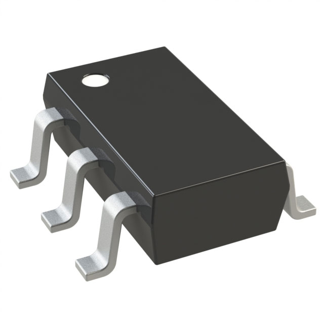
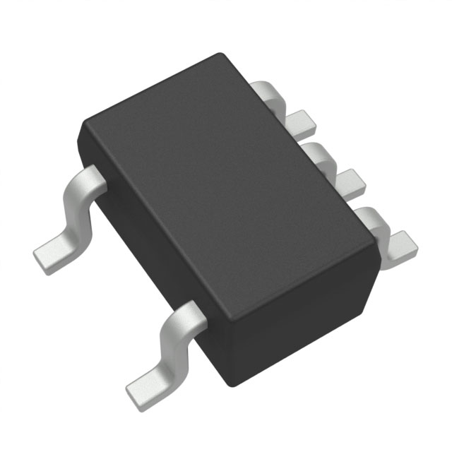
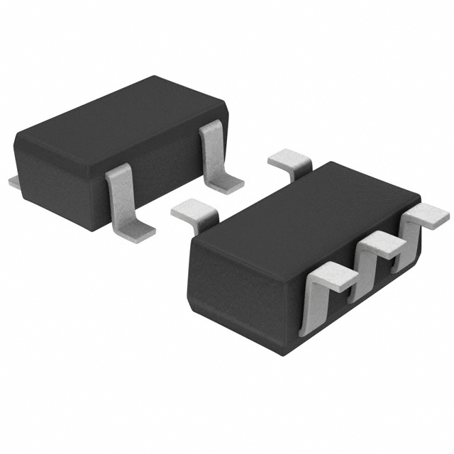
- If you’re building from blocks: instrumentation amplifier + high-resolution ADC (popular amp part numbers include INA125, INA333, AD8421).
C. The “boring” parts that prevent drama:
- Clean excitation/reference for the weight sensor bridge
- Proper grounding/shielding, cable strain relief, and EMI filtering
- Mechanical mounting that doesn’t side-load the sensor (side-loads are the plot holes of weighing systems)
Quick selection cheat sheet (practical):
- If your weight sensor is a classic 4-wire bridge load element and you want an easy life → HX711 or NAU7802 class solution.
- If your weight sensor needs higher speed, better rejection, more control → ADS1232/ADS1234 class.
- If your weight sensor system is “serious lab / serious industry” → AD7190 / ADS124S08 class with robust references and filtering.
- If you only need “is there weight?” and cost is king → FSR-type weight sensor, read with a simple ADC input + resistor divider (but accept lower accuracy).
Now let’s earn the happy ending.
2) What is a weight sensor (and what it is not)
A weight sensor is any device that converts the force from mass (weight under gravity) into a measurable signal—usually a change in resistance, capacitance, voltage, or frequency. In electronics terms, a weight sensor is the opening scene: it introduces a tiny signal and then asks the rest of your circuit to not ruin it.
What a weight sensor is:
- A transducer that produces a signal related to applied load
- Often a strain-based element that changes resistance when deformed
- The foundation of scales, dosing systems, hoppers, industrial batching, smart shelves, and “did my package actually get heavier or did my cat sit in it?”
What a weight sensor is not:
- A complete weighing system by itself (unless it includes mechanical structure, excitation, signal conditioning, and calibration inside)
- A guarantee of accuracy without proper mounting and calibration
- A magical truth machine that ignores temperature, creep, cable noise, and your coworker leaning on the bench
Here’s the fun part: most “weight sensor problems” are actually system problems. The weight sensor is innocent; it’s just trying to live its best life while your power supply ripple and your wobbly mount sabotage the storyline.
.png?x-oss-process=image/auto-orient,1/quality,q_70/format,webp)
3) How a weight sensor works: from atoms to ADC counts
Let’s take the most common “serious” weight sensor: the strain-gauge bridge type.
3.1 The bending-metal-to-resistance trick
A strain gauge is a patterned conductor bonded to a metal element. When the metal flexes under load, the conductor stretches or compresses. Its resistance changes a little. Like, really little. This is why a weight sensor is basically the “whispering character” in the cast: if the rest of the circuit shouts, nobody hears it.
The relationship is often described by:
- ΔR/R = GF × strain, where GF is the gauge factor (often around ~2 for common foil gauges).
3.2 The Wheatstone bridge: the classic ensemble
Most strain-based weight sensor elements use a Wheatstone bridge. Why? Because it:
- Converts tiny resistance changes into a differential voltage
- Cancels some common-mode noise
- Can be temperature-compensated when gauges are arranged cleverly
A full-bridge weight sensor output is typically:
- A few mV/V at full scale (example: 1–3 mV/V is common)
- So if you excite the bridge with 5 V, you might get only 5–15 mV at full rated load
That’s not “small.” That’s “please don’t sneeze near the cable.”
3.3 Excitation voltage: the quiet “powering the magic” step
The bridge needs excitation (often 3.3 V or 5 V). Stability matters because the output is proportional to excitation. A wobbly excitation makes your weight sensor look like it’s hallucinating.
Two common strategies:
- Ratiometric measurement: ADC reference tracks the same excitation. Supply changes cancel out.
- Precision reference + regulated excitation: Better absolute stability, often needed for high-accuracy systems.
3.4 Turning differential voltage into digital data
This is where the 24-bit ADC chips earn their paycheck. Parts like HX711, NAU7802, ADS1232, ADS1234, AD7190, AD7705, ADS124S08 are popular because they:
- Handle low-level differential signals
- Provide programmable gain
- Include digital filtering
- Offer noise rejection (often at 50/60 Hz mains)
And now your weight sensor whisper becomes a stream of numbers you can actually work with.
4) Weight sensor types: pick your character class
Think of weight sensor types like characters in a big ensemble series—each has strengths, flaws, and a very specific role in the plot.
4.1 Strain-gauge bridge weight sensor (load-cell style)
Best for: accuracy, repeatability, real weighing
Typical uses: scales, batching, hoppers, inventory shelves
Pros: stable, precise, wide range, well-understood
Cons: needs careful analog design + mechanical mounting
4.2 Single-point beam weight sensor
Often used in platform scales. Mechanically friendly when mounted correctly.
Pros: simple structure
Cons: side-load sensitivity, mounting mistakes are common
4.3 Shear beam / bending beam weight sensor
Common in industrial systems.
Pros: rugged
Cons: still hates bad mounting
4.4 S-type tension/compression weight sensor
Great for hanging loads.
Pros: good for tension systems
Cons: needs good alignment
4.5 Piezoelectric force/weight sensor
Best for: dynamic changes, impacts
Pros: high sensitivity for dynamic force
Cons: not ideal for static weight over long time (charge leakage)
4.6 Capacitive weight sensor
Best for: certain designs needing high resolution
Pros: can be very sensitive
Cons: humidity, contamination, mechanical complexity
4.7 FSR-type (force-sensitive resistor) “weight sensor”
Best for: presence detection, relative changes, human interaction
Pros: cheap, simple electronics
Cons: non-linear, drift, temperature sensitivity, poor absolute accuracy
Rule of thumb:
If the story requires truth (billing, dosing, compliance), pick a strain-gauge weight sensor.
If the story requires vibes (“something is on the seat”), FSR-style weight sensor can work.
.png?x-oss-process=image/auto-orient,1/quality,q_70/format,webp)
5) Key specifications that actually matter
Datasheets can feel like epic fantasy appendices. Here’s the “what actually changes your life” list for a weight sensor system:
5.1 Rated capacity & safe overload
- Pick a weight sensor capacity with margin.
- Overload rating tells you how much abuse it survives.
- If your environment includes “humans,” assume overload events will occur.
5.2 Sensitivity (mV/V)
Common strain-based weight sensor sensitivity: 1–3 mV/V.
Higher sensitivity = easier electronics, but not always better if noise dominates.
5.3 Nonlinearity, hysteresis, repeatability
These define how “honest” the weight sensor is across the range.
5.4 Creep & creep recovery
Creep is the slow drift under constant load.
This is the villain that shows up halfway through the season and ruins your calibration montage.
5.5 Temperature effects
Two big ones:
- Temp effect on zero (reading shifts with temperature even at no load)
- Temp effect on span (slope changes)
5.6 Output noise & resolution (system level)
Resolution is not just “24-bit ADC.”
Your weight sensor resolution depends on:
- ADC noise at chosen sample rate
- Bridge excitation stability
- Grounding and cabling
- Mechanical stability
5.7 IP rating and environmental sealing (if relevant)
Dust, humidity, washdown—your weight sensor can’t do accuracy if it’s busy being corroded.
6) Electronics around a weight sensor: the “supporting cast”
A weight sensor system is like a heist crew. The weight sensor is the safecracker—delicate, brilliant, and furious if you rush it. The rest of the components are the team that keeps it alive.
6.1 Bridge excitation and reference
Option A: Ratiometric (most common, very practical)
- Excite the weight sensor bridge with the same rail used as ADC reference
- Measurement becomes immune to that rail’s drift (within limits)
Option B: Precision reference + regulated excitation
- Better for multi-sensor systems and long-term stability
- Costs more attention and parts
6.2 ADC choices for weight sensor signals (popular part numbers)
- HX711: famously common, easy, low cost
- NAU7802: common in modern hobby/pro products
- ADS1232 / ADS1234: strong industrial bridge ADC family
- AD7190 / AD7705: high-resolution options used in precision contexts
- ADS124S08: flexible, robust, lots of configuration
(Yes, you can do it other ways, but these show up again and again in real designs.)
6.3 Gain stage (if needed)
If you’re not using a bridge ADC with built-in PGA, you’ll need amplification:
- INA125: classic “bridge + amp” style part number
- INA333: low-offset instrumentation amp style
- AD8421: instrumentation amplifier option for precision designs
Then pair with a high-resolution ADC.
6.4 Filtering (your weight sensor’s bouncer at the club)
A simple, effective approach:
- Differential RC filter at ADC inputs
- Common-mode filtering and shielding
- Digital filtering (moving average, IIR, FIR) tuned to your sample rate
6.5 Protection & robustness
A weight sensor cable can be an antenna, a static generator, and a “someone yanked it” event all at once.
Consider:
- ESD protection at connector entry
- Series resistors for input protection (if ADC allows)
- Good connectors + strain relief
6.6 The microcontroller / processor
You only need modest compute, but you do need:
- Stable timing
- Non-volatile storage for calibration coefficients
- Communication interface (UART/I²C/SPI/CAN/RS-485 as needed)
Popular controller part numbers often used in such systems include STM32F103, STM32F401, ATSAMD21, ATmega328P, RP2040, ESP32 (noting: these are part numbers/platform chips; you can choose equivalents easily).

7) How to choose a weight sensor for real applications (with scenarios)
Let’s do this like a streaming-series pitch meeting. You’re the producer, and the weight sensor is auditioning.
Scenario A: A shipping scale (needs repeatability, not Nobel-level accuracy)
You care about:
- Capacity and overload tolerance
- Reasonable temperature stability
- Decent resolution at slow sample rates
Typical approach:
- Strain-gauge weight sensor + HX711 class ADC
- Digital filtering + two-point calibration
- Strong mechanical mounting
Scenario B: A batching hopper (industrial, noisy environment)
You care about:
- EMI immunity
- Rugged mechanics
- Good drift and creep performance
- Serviceability
Typical approach:
- Industrial-grade strain-gauge weight sensor
- ADS1232/ADS1234 or ADS124S08 class ADC
- Shielded cable, proper grounding, strong enclosure design
Scenario C: A “smart shelf” inventory system (many sensors)
You care about:
- Multi-channel scaling
- Consistent calibration workflow
- Long-term drift management
- Networked data
Typical approach:
- Multiple weight sensor channels
- Either multiple ADCs or multiplexed architectures
- Good ratiometric strategy and temperature compensation
Scenario D: A seat occupancy / presence system
You care about:
- “Someone is there” detection
- Cost and simplicity
- Not necessarily accurate kilograms
Typical approach:
- FSR-type weight sensor + divider + ADC pin
- Smoothing + thresholding + hysteresis in software
8) Mechanical integration: the plot twist everyone ignores
If you’ve ever seen a show where the smartest character gets taken out by something absurd—like slipping on a banana peel—that’s what bad mechanics does to a perfectly good weight sensor system.
8.1 Avoid side loads and torsion
Most strain-based weight sensor elements are designed for load in a specific direction. Side loads cause:
- Nonlinearity
- Hysteresis
- Drift
- “It worked on the bench” syndrome
8.2 Mounting surfaces must be flat and stiff
Flex in the mount turns your weight sensor into a storyteller who changes details every time you ask.
8.3 Use proper load introduction
Load should apply where the weight sensor expects. Off-center loads can dominate your error budget.
8.4 Cable strain relief matters
A tug on the cable can look like a change in weight (micro-bending, connector stress). Give your weight sensor cable a calm life.
8.5 Thermal gradients are sneaky
A heater on one side, AC draft on the other, and suddenly your weight sensor has opinions about physics.
.png?x-oss-process=image/auto-orient,1/quality,q_70/format,webp)
9) Calibration & software: turning raw counts into truth
A weight sensor produces counts. People want kilograms (or pounds). Software is the translator—and sometimes the therapist.
9.1 The minimum viable calibration: two-point
1) Record raw reading at zero load (offset)
2) Apply a known weight and record reading (span)
3) Compute slope
4) Convert new readings:
weight = (raw − offset) × slope
This works surprisingly well for many weight sensor products.
9.2 Multi-point calibration (when you need better accuracy)
Use several known weights across the range:
- Fit a line (or piecewise linear curve)
- Optionally add temperature terms
9.3 Filtering: don’t “average” your way into lag
Common digital filters:
- Moving average (simple, adds lag)
- Exponential moving average (EMA)
- Median filter (great for spike removal)
- FIR low-pass (predictable behavior)
A practical recipe for a weight sensor UI:
- Median-of-3 to kill spikes
- Then EMA for smooth display
- Use raw/less filtered stream for control loops if needed
9.4 Tare and zero tracking
- Tare: user says “this is my new zero”
- Zero tracking: slowly adjust offset when near zero and stable
Be careful: aggressive zero tracking can “erase” small true loads. Your weight sensor didn’t lie; your algorithm did.
9.5 Temperature compensation (simple and effective)
If you have a temperature reading near the weight sensor:
- Model offset drift vs temperature
- Model span drift vs temperature
- Store coefficients
Even a crude linear compensation can dramatically improve perceived stability.
10) Noise, drift, creep, and other villains (with counterspells)
Villain #1: EMI / mains hum (50/60 Hz)
Symptoms: reading buzzes, periodic ripple
Counterspells:
- Shielded cable, proper grounding
- Differential input filtering
- Choose ADC sample rates / notch filters aligned to mains
- Keep weight sensor cables away from switching supplies and motor lines
Villain #2: Ground loops
Symptoms: weight changes when other equipment turns on
Counterspells:
- Single-point grounding strategy
- Isolated communication if needed
- Avoid referencing the weight sensor return through power ground paths
Villain #3: Creep
Symptoms: load applied, reading drifts slowly
Counterspells:
- Use a better weight sensor element if this matters
- Warm-up time and stabilization
- Software: allow settling before “final” reading
Villain #4: Temperature gradients
Symptoms: drift correlated with HVAC cycles, sunlight, nearby heaters
Counterspells:
- Shield and insulate
- Put temperature sensor near the weight sensor
- Compensate in software
Villain #5: Mechanical relaxation / mounting stress
Symptoms: “works until it’s assembled”
Counterspells:
- Re-evaluate mounting torque, alignment, and load introduction
- Use proper spacers and rigid surfaces
- Remove cable forces from the weight sensor body
Villain #6: Power supply ripple
Symptoms: noise changes with DC-DC load or switching frequency
Counterspells:
- Better analog rail filtering
- Ratiometric design
- Keep the weight sensor analog area separate from noisy digital zones
.png?x-oss-process=image/auto-orient,1/quality,q_70/format,webp)
11) Troubleshooting a weight sensor system: fast diagnosis matrix
When a weight sensor system misbehaves, don’t panic. Run this like a detective episode—collect clues, eliminate suspects.
11.1 Quick symptoms → likely causes
| Symptom | Likely cause | First fix |
|---|---|---|
| Reading jumps when you touch the cable | Shield/ground/strain relief issue | Improve shielding, add strain relief, check connector |
| Slow drift under constant load | Creep or thermal drift | Wait for settling, add temperature compensation |
| Periodic ripple (looks like a sine wave) | Mains pickup | ADC notch setting, cable shielding, grounding |
| Reading saturates near full scale | Gain too high or wiring wrong | Check bridge wiring, reduce gain |
| Reading changes when nearby motor runs | EMI coupling | Separate cables, add filtering, improve ground |
| Non-repeatable readings after assembly | Mechanical stress | Rework mounting, eliminate side load |
11.2 Wiring sanity checks (for bridge weight sensor)
- Confirm bridge excitation present and stable
- Confirm differential inputs are not swapped (some swaps invert sign; that’s okay if consistent)
- Confirm shield termination strategy (usually one end)
- Confirm no intermittent connector pins
11.3 “Is it the weight sensor or the electronics?”
A fast isolation trick:
- Replace the weight sensor temporarily with a known resistor network that simulates a bridge imbalance
- If your readings stabilize → your weight sensor or mechanics may be the issue
- If still noisy → electronics/grounding/filtering is guilty
11.4 The “it only fails in the field” checklist
- Temperature extremes
- Long cables
- Nearby high-power switching
- Moisture ingress
- Mechanical vibration
- Poor power quality
A weight sensor system is not just a circuit; it’s an ecosystem.
12) Reference designs & popular part numbers (no vendor names)
Below are practical, repeatable design patterns that show up in real products. Part numbers included (no vendor names).
Design A: Simple digital bridge ADC + microcontroller
Use case: consumer scale, moderate industrial, prototypes that become products
Core:
- Bridge ADC: HX711 or NAU7802 or ADS1232
- Controller: STM32F103 / ATmega328P / RP2040 / ESP32 (pick your comfort zone)
Typical supporting parts:
- Low-noise LDO (choose a low-noise, low-drift regulator class)
- RC input filter (differential + common-mode)
- ESD protection at connector
- TVS on power input if field wiring is long
Why it works:
Minimal analog design risk. The ADC is built for weight sensor bridges.
Design B: Instrumentation amp + high-resolution ADC (modular but powerful)
Use case: precision systems, custom sampling, more control
Core:
- Instrumentation amp: INA125, INA333, or AD8421
- ADC: AD7190, AD7705, ADS124S08
- Reference/excitation: ratiometric or precision reference architecture
Why it works:
You get flexibility: gain, bandwidth, filtering strategy. Great when your weight sensor needs special handling.
Design C: Multi-channel weight sensor “smart shelf”
Use case: inventory tracking, warehouse bins, retail smart fixtures
Core:
- Multiple bridge ADC channels (either one per weight sensor or careful multiplexing)
- Controller with enough IO and data pipeline
- Optional temperature sensing per zone
- Network interface (RS-485/CAN/Ethernet/Wi-Fi depending on environment)
Key engineering idea:
Your calibration workflow must scale. The hardest part isn’t the weight sensor—it’s managing a fleet of them.
Practical BOM checklist (generic, reuse-friendly)
- Bridge ADC / amplifier stage
- Stable excitation/reference strategy
- Input RC network + shielding plan
- Clean power regulation (analog + digital partition)
- Connector + strain relief
- Calibration storage (internal flash or external EEPROM)
- Enclosure grounding and cable routing plan
If you do nothing else: treat your weight sensor input like an RF input. Because to noise, it basically is.
.png?x-oss-process=image/auto-orient,1/quality,q_70/format,webp)
13) FAQ: weight sensor questions people actually ask
Q1) Why does my weight sensor reading drift even when nothing changes?
Because “nothing changes” is a myth. Temperature, creep, mounting stress, and power supply drift all move the needle. For a weight sensor, drift is not personal—it’s physics. Use warm-up time, better mechanics, and temperature compensation.
Q2) Is a 24-bit ADC automatically high accuracy for a weight sensor?
No. A 24-bit number can still be a 24-bit lie if noise, grounding, and mechanics are messy. A weight sensor system’s effective resolution is the whole chain: bridge, excitation, layout, ADC noise at your chosen rate, and filtering.
Q3) Can I use a weight sensor with long cables (5–20 meters)?
Yes, but you must design for it: shielding, grounding strategy, input filtering, ESD protection, and robust connectors. Long cables turn your weight sensor into an antenna.
Q4) How often should I recalibrate a weight sensor system?
Depends on required accuracy and environment. For stable indoor systems, periodic calibration may be enough. For harsh or regulated contexts, schedule calibration and log it. If your weight sensor is in a place with heat cycles and vibration, recalibrate more often.
Q5) What’s the difference between a weight sensor and a force sensor?
A weight sensor measures force due to gravity (mass × g) in a weighing setup. A force sensor can measure any force direction and dynamic loads. Many devices can be either, depending on mounting and calibration.
Q6) Why does my weight sensor show different readings when the load is off-center?
Because off-center load introduces moments and side forces. Many weight sensor elements assume a specific load path. Fix with better load introduction and mechanical design.
Q7) Can I use an FSR as a weight sensor for accurate scales?
You can, but it’s usually a bad idea for accurate weighing. FSR-type weight sensor elements drift and are non-linear. They’re great for detection, not for billing by grams.
Q8) My weight sensor output is noisy. Should I just average more?
Averaging helps, but it’s not a cure. Fix root causes first: shielding, grounding, filtering, stable excitation, mechanical stability. Then apply sensible filtering.
Q9) How do I implement tare properly?
Tare is simply storing the current weight sensor reading as “zero offset.” Protect against accidental tare: require stability (low variance) before accepting tare.
Q10) How do I stop the reading from changing when the power supply load changes?
Use a ratiometric design (ADC reference tied to weight sensor excitation), improve power filtering, and separate noisy digital loads from the analog front end.
14) Wrap-up: your weight sensor system, but stable
A weight sensor is deceptively simple: apply load, get a number. And yet building a great weight sensor product is like writing a long-running series: the pilot can be easy, but season two is where you learn whether your story holds up under pressure.
If you remember only three things:
1) A weight sensor is a system—mechanics + excitation + analog front end + filtering + calibration.
2) Your best upgrades are often boring: mounting, shielding, grounding, stable rails.
3) Pick proven building blocks (like HX711, NAU7802, ADS1232, ADS1234, AD7190, AD7705, ADS124S08, plus amps like INA125, INA333, AD8421) and spend your creativity where it matters: mechanics, calibration workflow, and reliability.

Related Articles
- ·Flex Fuel Sensor: How to Choose the Right One for ECU Integration
- ·How to Choose the Right Knock Sensor for Engine Control and Industrial Monitoring
- ·Capacitor Thin Film Temperature Sensor: Measuring Heat Like a Sci-Fi Minimalist
- ·Passive Infrared Sensor (PIR): The Engineer’s Playfully Serious Guide to Motion Detection
- ·Weight Sensor (Weight Sensor, Weight Sensor, Weight Sensor): The Playfully Serious Engineer’s 2026 Guide to Measuring Mass Like a Pro
- ·Inductive Proximity Sensors Explained: Why Inductive Proximity Sensors Power Industrial Automation
- ·Electrochemical Gas Sensor Explained: Why Electrochemical Gas Sensors Are the Quiet Heroes of Gas Detection
- ·Parking Sensors Explained: How Parking Sensors See the Invisible and Save Your Bumpers
- ·Color Sensors: The Not-So-Secret Agents of Modern Electronics
- ·Environmental Sensor — A Practical, Parts-Savvy, Pop-Culture-Sprinkled Guide
 FAQ
FAQ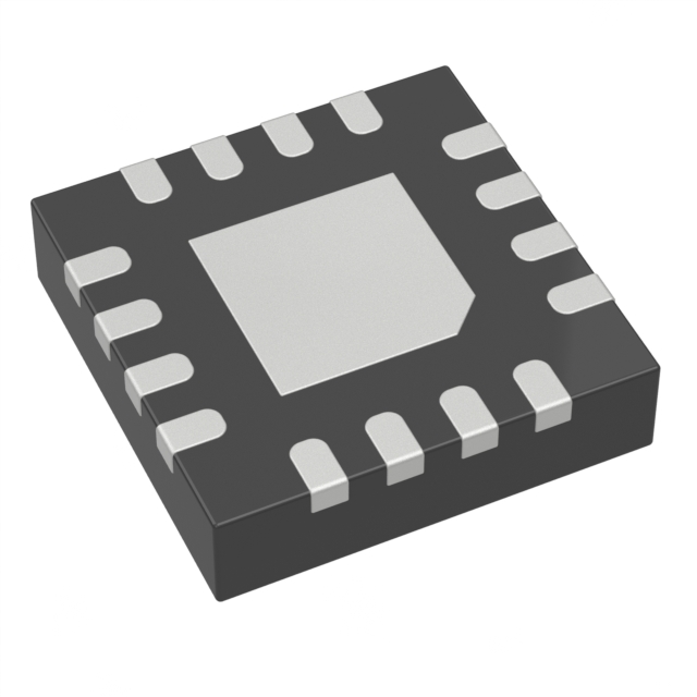





.png?x-oss-process=image/format,webp/resize,h_32)


