

Hospital Bed Electronics: Tiny Boards, Big Comfort (and Even Bigger Safety)

“If Tony Stark had to design a hospital bed, he’d start with the motor drivers.”
Jokes aside, modern hospital bed electronics are a wonderful mash-up of motion control, safety engineering, low-noise sensing, secure connectivity, and ultra-boring-on-purpose power design. In this guide we’ll unpack the whole stack—from actuators and H-bridges to nurse-call interfaces, IEC 60601-1 isolation, anti-entrapment sensors, battery backup, firmware failsafes, and even a dash of edge AI that spots a dangerous roll-out before it happens. Think Grey’s Anatomy bedside vibes with The Mandalorian level reliability.
Table of Contents
1) Overview: What Makes a Smart Bed Smart
A hospital bed isn’t just a frame with motors—it’s a motion platform with a sensor network, fault-tolerant power rails, medical-grade isolation, and interfaces that let clinicians, patients, and facility systems cooperate without surprises. The star cast:
- Motion: 3–6 linear actuators (head, knee, height, Trendelenburg/Reverse-Trendelenburg, back articulation, leg).
- Electronics: H-bridge/half-bridge drivers, current sensing, hall/optical encoders, limit switches.
- Safety: rail position switches, anti-entrapment light curtains or capacitive strips, bed exit via load cells or pressure mats, CPR quick-drop solenoid.
- Power: medical SMPS with 2×MOPP isolation, PFC, low leakage; LiFePO₄ or SLA backup; fuel gauge; brown-out strategy.
- Comms: nurse-call relay, RS-485/LIN/CAN in the bed, optional BLE/Wi-Fi gateway to hospital network (through approved bridge).
- Brains: 1 main MCU for motion + safety loop, 1 low-power MCU that never sleeps (watchdog/alert), optional MPU/SoC for UX/telemetry.
- Proof: logs with timestamps (ISO 80601-2-52 context), event counters, maintenance hours, E-stop history.
If Stranger Things taught us anything, it’s that monsters hate light and logs. Your bed needs both.
2) Industrial-Grade Wish List (Requirements & KPIs)
- Noise: < 45 dBA at 1 m during repositioning (night shifts matter).
- Speed: 20–40 mm/s typical actuator stroke; controlled ramp-up/ramp-down for comfort.
- Repeatability: ±2–3 mm at end position with dual feedback (encoder + limit).
- Load: 230–270 kg working load; overload detect at 110–120% with graceful abort.
- Uptime: MTBF to match motor life; firmware OTA only through service dock or signed USB; clinical network never bricked by bedside.
- Safety loop: < 10 ms detection for rail drop, entrapment, jam current spike.
- Power: mains 100–240 VAC, 50/60 Hz; leakage current per IEC; battery runtime ≥ 30 minutes of typical motion plus alarm.
- EMC: pass IEC 60601-1-2 with radios off/on; immunity while motors run, not just idle.
- Usability: large tactile buttons, backlight, one honest button to flat for CPR.
- Cleanability: IPX4–IPX6 spray test, chemical resistance for disinfectants; sealed keypads.
KPIs are not plot armor; measure them like Money Heist plans every minute.
.png?x-oss-process=image/auto-orient,1/quality,q_70/format,webp)
3) System Architecture (Block-by-Block)
Mechanical + Power Domain
- AC inlet → medical SMPS (PFC + 2×MOPP) → 24 V bus
- 24 V → buck rails (12 V motors if required), LDOs for AFEs/sensors
- Battery pack (LiFePO₄/SLA) via smart charger + ideal-diode ORing
- Fuel gauge with coulomb counting; brown-out supervisor
Motion Domain
- MCU A (Real-time): motion kernel + safety loop
- Gate drivers/H-bridges per actuator; current shunt + op-amp/TIA
- Hall sensors/encoders; limit switches (redundant)
Sensing Domain
- Load cells (4-point bed exit), tilt IMU, rail microswitches, capacitive strip for entrapment, optional ToF light curtain
- AFEs: instrumentation amps, delta-sigma ADCs, filters
Comms & UX
- Nurse-call relay (dry contact) + safety opto-isolation
- Intra-bed bus: LIN or CAN-FD; external: RS-485; optional BLE to a gateway
- Handset/side panel: membrane keypad + LED bar + haptic tick
- Service port: galvanically isolated USB-C or magnetic pogo
Security & Logs
- Secure boot (if MPU present), config signing, rolling counters
- Event log in FRAM/Flash: “rail unlocked,” “motor current jam,” “CPR mode,” “battery low,” “OTA accepted”
Think of the architecture as a Lord of the Rings fellowship—each block must pull its weight without corrupting the ring (the patient).
4) Motion: Actuators, Motors, Drivers & Position Feedback
4.1 Actuator Choices
- DC brushed linear actuators: simple, cheap, EMI tame with snubbers; brushes wear, but for beds it’s fine.
- BLDC linear or servo columns: smoother, higher life, costlier, needs FOC or smart module.
- Gas-spring assist for head/knee reduces current spikes.
4.2 Drivers
- H-bridge MOSFETs with current-sense (low-ohm shunt + INA)
- PWM at 20–30 kHz to push switching out of audible band
- Soft-start/stop ramps, slew-rate control to tame EMI
- Back-EMF brake and coast modes for different motions
- Thermal foldback at driver & motor thermistor readout
4.3 Feedback & Limits
- Hall quadrature or optical encoders for position; absolute home via limit switch
- Dual-channel end-stop (functional safety lite): both switch & current spike agreement to declare stall
- Torque proxy: motor current vs speed; detect pinch in < 100 ms
- Position profiles: store “favorite” reclines (like Friends recliner episode), but verify rails locked first
4.4 Cables & Connectors
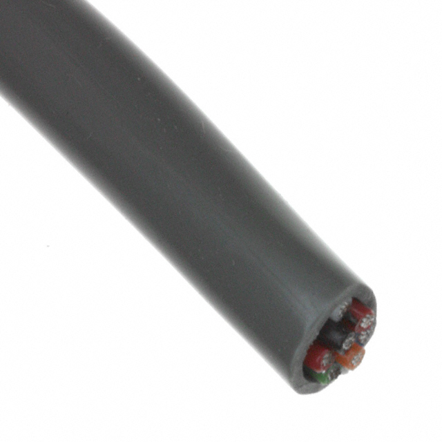
- Locking, keyed, color-coded; strain relief; 360° shield terminations at metalwork
- Route motor cables away from sensor AFEs; separate quiet and loud harnesses
.png?x-oss-process=image/auto-orient,1/quality,q_70/format,webp)
5) Sensing Suite: Weight, Presence, Rails, Tilt, Vitals Adjacent
5.1 Bed-Exit by Load Cells
- 4 shear beams under corners → IA + ΔΣ ADC → digital filter
- Auto-zero post-linen change; drift guard for thermal swings
- Compute Center of Pressure (CoP) to foresee roll-out; if CoP migrates to rail and tilt rises, pre-alarm gently.
5.2 Rail & Entrapment
- Rail up/down microswitches (redundant), state in logs
- Capacitive strip or IR light curtain across gap zones; if motion and strip triggered → cut torque & reverse 20 mm.
5.3 Tilt & Angle
- 3-axis IMU or dual inclinometers; calibrate gravity offset with bed empty; use for Trendelenburg limits and transfer assist.
5.4 Environment
- Ambient light for keypad backlight; temperature near drivers; humidity to pace condensation risk in sealed housings.
5.5 “Vitals Adjacent”
- Some beds host accessory ports for SpO₂/ECG pods. Keep patient-applied parts electrically isolated (separate PSU or medical isolation transformer) and never let bed motors share that ground.
6) Power Architecture: AC Mains, Medical SMPS, Battery, Thermal
6.1 Medical Mains
- IEC 60601-1 compliant supply, 2×MOPP, PFC, low leakage; surge protectors/TVS at inlet
- Earth bond test points; Y-caps sized for leakage targets; inrush limiter (NTC or active)
6.2 Low-Voltage Rails
- 24 V bus → buck to 12 V (legacy actuators) → 5 V, 3.3 V, 1.8 V
- LDOs for analog AFEs; RC filters at ADC refs; star grounds splitting motor, logic, analog returns
6.3 Battery & Backup
- LiFePO₄ pack preferred (safety, cycle life); SLA remains common (capex)
- Charger with temp-comp curves; ideal diode ORing to avoid back-feed
- Fuel gauge with state-of-health; brown-out playbook: stop motion, log, keep comms and amber indicator alive for 30 min.
6.4 Thermal
- Drivers on copper pours with stitched vias; heat spreader to chassis; keep IMU/AFEs thermally away from drivers
- If a fan is used, mount elastomer grommets to keep dBA low; fans and nurses are frenemies.
.png?x-oss-process=image/auto-orient,1/quality,q_70/format,webp)
7) Safety & Compliance: IEC 60601-1/-1-2, Risk & Usability
- Creepage/clearance: follow tables for altitude/pollution degree
- Protective earth and enclosure leakage meet limits; document worst-case
- Single fault: remove one limit switch and prove firmware still prevents crush (current spike + time)
- Usability (IEC 62366): rail indicator lights readable in daylight and at 3 AM
- Risk management (ISO 14971): hazards list → mitigations → verification
- Labels & IFU: warnings for accessories; max load; cleaning agents allowed
If Barbie was about compliance, it would still be pink—but every clearance would be exact.
8) Connectivity: Nurse-Call, LIN/CAN/RS-485, BLE/Wi-Fi
- Nurse-call: dry contact relays for call/alert; maintain galvanic isolation; debounce; test via panel self-check
- Intra-bed network: LIN for handsets/actuators; CAN-FD for modularity; RS-485 to the headwall if needed
- Wireless: BLE to bedside gateway for logs; Wi-Fi only through approved bridge with WPA2-Enterprise; never expose the bed MCU directly
- Security: bed serial identity, signed configs, no unauthenticated commands (no “Alexa, lean 30°” horror scenes)
.png?x-oss-process=image/auto-orient,1/quality,q_70/format,webp)
10) Firmware & Edge AI: Prevent, Predict, Prove
- RTOS with separate Safety Task (highest prio), Motion Task, UX Task, Logging Task
- Watchdogs (windowed) + brown-out + clock fail monitors
- Finite State Machines for each actuator: Idle → Seeking → Braking → Fault → Recover
- Model-light analytics (TinyML): trend CoP, tilt, movement variance to warn roll-out 30–90 s earlier (false-positive tuned)
- Config & Presets: versioned; CRC; write-once staging then commit
- Service Mode: motor learn, rail sensor test, nurse-call test; export JSON log to service stick
- Cyber: if there’s a Linux SoC, use secure boot, read-only rootfs, signed updates, drop-priv daemons, firewall default-deny
Logs are your courtroom scenes from Suits—timelines win arguments.
.png?x-oss-process=image/auto-orient,1/quality,q_70/format,webp)
11) EMC & Layout: Make the Lab Boring
- Zones: loud (motors/drivers) vs quiet (AFEs/ADC) vs digital (MCU/Comms)
- Grounding: chassis at single point; shields terminated 360°; avoid pigtails
- Snubbers/TVS on motor lines; common-mode chokes on I/O; RC on switches
- Plane continuity under AFEs; slotting around motor connectors
- Cable set: twisted pair for motor leads; keep loops small; ferrite beads where needed
- Test while moving and transmitting, not just museum-idle.
12) Verification & Validation: From E-Stop to Egress Logs
- Motion: travel accuracy, stall detect ≤ 100 ms, recovery profile
- Safety: entrapment test with calibrated dummy; rail unlock abort; CPR single-press path time
- Power: battery runtime with repeated motions; brown-out log integrity; charger thermal soak
- EMC: emissions/immunity with worst-case PWM; ESD on handset and rail buttons
- Software: unit tests for FSM transitions; fault injection; long-haul 72-h cycle
- Usability: 30-sec tasks with naive users (find “flat,” call nurse)
.png?x-oss-process=image/auto-orient,1/quality,q_70/format,webp)
13) Deployment & Field Notes: Life in the Ward
- QR pairing for handset to bed (LIN address assign)
- Night mode dims LEDs; silent boot
- Cable relief for rails that fold; keep flex cycles ≥ 20k
- Cleaning: no holes facing up; vent labyrinths; conformal coat PCBs; gasketed housings
- Spare strategy: handset, PSU module, actuator are field-replaceable units (FRUs)
14) Failure Modes & Serviceability: “No Tools at 2 AM”
- Actuator jam: detect via current; reverse 20 mm; log
- Rail sensor flaky: lock motion, keep bed flat, alert
- Battery low or SOH poor: disable nonessential moves, maintain nurse-call
- Handset cable damage: fall back to side-panel; magnetic connector helps save ports
.png?x-oss-process=image/auto-orient,1/quality,q_70/format,webp)
15) Sample BOM (By Function)
Motion
- Linear actuators (3–6), DC or BLDC
- H-bridge drivers (30–60 A peak), gate drivers, MOSFETs
- Shunt resistors (low-ohm), current-sense amplifiers
- Hall/optical encoders, limit switches, motor NTCs
Sensing
- Load cells (4×), instrumentation amps, ΔΣ ADC
- Rail microswitches; capacitive or IR strip modules
- IMU/inclinometer; ambient light; temperature sensors
Power
- Medical SMPS (24 V), PFC, 2×MOPP
- Battery pack (LiFePO₄/SLA), charger, fuel gauge
- Ideal diode ORing, TVS, fuses, common-mode chokes
Compute/Comms
- Main MCU (Cortex-M or similar), secondary low-power MCU
- LIN/CAN/RS-485 transceivers; opto-isolators where required
- Optional BLE/Wi-Fi module (used through gateway)
UX
- Membrane keypad, backlight drivers, haptic motor driver
- LED bargraph, buzzer, light pipes
Mechanical & Interconnect
- Shielded harnesses, keyed connectors, gaskets, EMI cans, heat spreaders
16) Glossary (Rapid Fire)
- 2×MOPP: Two Means of Patient Protection (insulation/isolation).
- CoP: Center of Pressure, used to predict roll-out.
- H-bridge: Bidirectional motor driver topology.
- IEC 60601-1/-1-2: Medical electrical safety/EMC standards.
- LIN/CAN: Automotive-style serial buses for devices.
- LiFePO₄: Safer lithium chemistry with long cycle life.
- Trendelenburg: Bed tilt position where feet are above the head.
One-line takeaway: Hospital bed electronics are where comfort meets compliance—deliver quiet torque, honest sensors, clean power, and logs that read like a superhero origin story.
Engineering guide only—no clinical claims. Follow local regulations, standards, and institutional policies.

Related Articles
- ·ICD Electronics: Tiny Lightning, Relentless Reliability
- ·Smart Pill Dispensing Electronics: From Missed Doses to Mission Control
- ·Electrosurgery Electronics: Turning RF Into a Surgical Superpower
- ·Endoscopic Imaging Electronics: Tiny Optics, Big Picture
- ·X-ray & CT Electronics: From Kilovolts to Reconstruction
- ·MRI Core Electronics: From Quench to K-Space
- ·IVD Electronics: Tiny Signals, Big Answers
- ·Vital Signs Monitor Electronics: Tiny Signals, Big Decisions
- ·Neurostimulator Electronics: Tiny Pulses, Big Nerves
- ·Pacemaker Electronics: Tiny Joules, Big Heart
 FAQ
FAQ




.png?x-oss-process=image/format,webp/resize,h_32)


