
ICD Electronics: Tiny Lightning, Relentless Reliability
Global electronic component supplier ERSAELECTRONICS: Rich inventory for one-stop shopping. Inquire easily, and receive fast, customized solutions and quotes.
Disclaimer: Engineering guide only—no clinical claims. ICD (Implantable Cardioverter-Defibrillator) devices are regulated active implants. Follow risk management (ISO 14971), software lifecycle (IEC 62304), usability (IEC 62366), electrical safety/EMC (IEC 60601-1/-1-2), and implantable requirements (AAMI/ISO 14708 series, incl. parts applicable to ICD/CRT-D). Nothing here replaces your quality system or notified-body guidance.
If Iron Man had a backup arc reactor the size of a matchbox, it would be an ICD—quiet, vigilant, and capable of throwing a precisely-metered thunderbolt when the script calls for a plot twist. ICD electronics live where power is scarce, noise is forbidden, and timing is everything. The audience never notices the hero… until the save.
Table of Contents
1) The Mission: What an ICD Actually Does (without the hospital drama)
An ICD (Implantable Cardioverter-Defibrillator) is a small implant that continuously monitors cardiac rhythm, recognizes life-threatening arrhythmias like VT (ventricular tachycardia) and VF (ventricular fibrillation), and delivers therapy:
- ATP (Anti-Tachycardia Pacing): a burst of pace pulses to interrupt reentry—low energy, “surgical whisper.”
- Cardioversion: a synchronized shock timed to a safe point in the cardiac cycle—medium energy, “intervention with manners.”
- Defibrillation: a non-synchronized high-energy shock to stop chaotic VF—“tiny lightning” with intent.
ICD electronics must sense rhythms with high fidelity, classify them with low latency, and execute therapy exactly when commanded. Think Mission: Impossible: the fuse is short, the room is loud, and you get one chance to be right.
2) Success Metrics: How ICD Electronics Win in the Real World
- Sensing integrity: high CMRR, micro-volt resolution, stable baselines despite motion/EMG, and lead impedance monitoring.
- Detection reliability: robust ICD VT/VF discrimination (rate, stability, onset, morphology, multi-vector logic) with low false-positive therapy.
- Therapy timing: predictable latency from detection to ICD therapy; precise sync for cardioversion; blanking windows that don’t blind the device.
- Energy management: minimal quiescent draw; efficient high-voltage charging; battery life measured in years.
- Data & security: authenticated telemetry, encrypted updates, immutable logs (because future-you wants evidence).
- Biocompatibility & hermeticity: titanium can, ceramic feedthroughs, low leakage, MRI-conditional targets.
- Regulatory readiness: requirements traceability and objective evidence across the ICD lifecycle.
If a metric doesn’t move the needle on patient safety or ICD longevity, it’s probably a nice-to-have.
3) System Architecture: From Leads to Logic to Lightning
An ICD stack—simplified but honest:
- Leads & Header
Endocardial leads deliver sensing vectors and therapy. The header routes to feedthrough capacitors and ESD/EMI protection before touching silicon. - Analog Front End (AFE)
Ultra-low-noise differential amplifiers, programmable gains, analog filtering, blanking, and high-resolution ADC. Lead impedance test paths with tiny test currents. - Compute & Detection
A low-power MCU/DSP (often in an ASIC) runs ICD detection pipelines: rate counters, morphology templates, stability logic, and therapy decision trees. - Therapy Delivery
• Pacing path: H-bridge or current-limited output stage for brady pacing and ATP.
• High-voltage (HV) path: HV charger (flyback/inductive) → energy storage capacitor(s) → H-bridge or multiplexer → shock electrodes. - Power Management
Battery + protection → low-IQ regulators and references → analog & digital islands with strict sharing rules. - Telemetry
MICS-band transceiver (402–405 MHz) and/or inductive link for implants; possibly NFC for near-field setup; robust cryptography. - Time & Data
Crystal/RTC; FRAM/flash logs; error-corrected memory (ECC); secure boot. - Can, Feedthroughs & Filters
Titanium case is ground and RF shield; multilayer ceramic feedthroughs provide hermetic signals with built-in EMI control; laser-welded seams.
Pop-culture version: Dune stillsuits for power, Avengers for precise timing, Oppenheimer for energy control, and Andor for quiet, reliable ops. That’s ICD electronics.
.png?x-oss-process=image/auto-orient,1/quality,q_70/format,webp)
4) Sensing & Analog Front End: Quietly Hearing the Heart
The ICD has two jobs: never miss a true event; never cry wolf. The AFE is where both goals begin.
Front-end priorities
- Noise & CMRR: differential input with µV-level resolution; chopper-stabilized or zero-drift amps to tame offset; input bias currents in the pA-to-nA region.
- Programmable gain/filters: hardware high-pass (baseline wander), low-pass (EMG/RF), and notch (mains); digital fine-tuning post-ADC.
- Blanking windows: mask amplifier saturation during pacing/shocks; design faster recovery than your shortest interval of interest.
- Lead impedance & continuity: micro-current injection plus voltage measurement to detect fracture, insulation issues, or dislodgement.
- ESD/EMI defense: feedthrough capacitors at the can, series resistors, low-cap ESD clamps, careful return paths.
AFE building blocks (representative classes)
- Precision op-amps / chopper amps (think OPAx33x-class, LTC607x-class for lab work);
- Instrumentation amps (INA33x-class) for differential sensing;
- Low-leakage analog switches (ADG12xx-class) for vector selection;
- ICD-grade SAR ADCs in the tens to hundreds of kS/s at 12–16-bit with micro-power modes (ADS70xx/AD40xx-class);
- Precision references with sub-10 ppm/°C drift;
- Passive networks with medical-grade dielectric stability.
Engineering reality check: commercial ICD front-ends are typically custom ASICs. The parts above anchor benchtop prototypes and pre-silicon evaluations.
5) Detection Algorithms: VT/VF, Morphology, and Why False Positives Are Villains
ICD detection blends classical signal processing with heuristic safeguards:
- Rate zones: separate VT and VF zones with programmable thresholds and detection counters.
- Onset & stability: sudden onset + regularity favor VT; wandering irregularity suggests AF with rapid ventricular response (not a shock target).
- Morphology correlation: compare sensed waveform to a stored template; poor match at high rates supports VT.
- Dual-chamber logic (if applicable): A-V relationship can separate SVT from VT.
- Sensing vector management: pick the cleanest vector dynamically; suppress myopotential oversensing.
- Blanking & refractory: post-pace/shock windows prevent self-triggering and T-wave oversensing.
Latency budgets matter: ATP needs fast decisions; synchronized cardioversion must align to a safe point; defibrillation must not dawdle once VF is confirmed. ICD software treats milliseconds like gold coins.
6) High-Voltage Subsystem: Charging, Switching, and Delivering the ICD Shock
This is the fireworks department—designed by accountants and monks.
Energy store
ICD shocks draw on a compact HV capacitor bank with tight ESR/ESL spread and long-term stability. Medical vendors produce hermetic HV capacitors designed for implants; engineers model for aging, leakage, and temperature.
Charging
A micro-power flyback or related topology steps up battery voltage to several hundred volts. Efficiency matters (less heat, less time at elevated stress). Charging current profiles respect battery chemistry and device thermals.
Switching & delivery
HV-rated MOSFETs/IGBTs/HV switches route the stored energy as monophasic or biphasic waveforms across the selected electrodes.
Blanking and crowbar paths protect the AFE; snubbers/RC networks manage ringing and EMI.
ICD pacing/ATP path is separate: current-limited, precisely timed, often using an H-bridge that survives the HV neighborhood.
Instrumentation
Divider networks and HV ADC channels validate charge voltage before therapy; post-shock residuals are bleeded down safely; charge abort logic returns the ICD to listening mode without drama.
Bench parts you’ll see in labs (development fixtures): capacitor-charger controllers (LT375x-class), HV MOSFETs, precision dividers. Production ICD hardware typically integrates or customizes for implant duty.
.png?x-oss-process=image/auto-orient,1/quality,q_70/format,webp)
7) Power Source & Power Management: Batteries, Rails, and Micro-amps that Matter
Chemistry and lifetime
ICD batteries are specialized primary lithium chemistries (e.g., Li/SVO or hybrid stacks) chosen for long shelf life, high pulse capability, and predictable internal resistance growth. Energy budgeting includes worst-case charge-to-therapy cycles and telemetry.
Fuel gauging without drama
Classic coulomb counters struggle with low duty-cycle, high-pulse profiles. ICD electronics combine open-circuit voltage models, impedance tracking, and usage logs to estimate end-of-life with comfortable margin.
Rail discipline
- Analog island: ultra-quiet LDOs, no shared returns with switching nodes.
- Digital island: efficient buck or buck-boost with aggressive sleep states.
- HV island: physically and electrically segregated; keep di/dt where it belongs.
- Sub-µA references and supervisors; RTC domains that survive everything.
Thermal stewardship
ICD cans are small; even tens of milliwatts for long periods feel warm. Derate charging; time heavy tasks; log thermal excursions.
8) Telemetry, Security & Time: Talking to an ICD—MICS, Inductive, NFC, and Trust
Telemetry stacks
- MICS band (402–405 MHz): low power, tissue-friendly; used for remote monitoring and programming at modest data rates.
- Inductive coupling (kHz–MHz): short-range, high-reliability link for near-field sessions or emergency access.
- NFC: limited roles (pairing, ID), subject to can thickness and alignment.
Security posture
- Hardware root of trust (secure element or ROM-rooted boot), per-device keys, authenticated sessions, and encrypted payloads.
- Signed firmware with anti-rollback; immutable secure boot path; partitioned application domains so the ICD therapy engine is not roommates with the UI.
- Privacy: least-privilege data, rate-limited commands, exhaustive audit logs.
Time matters
Crystal-based RTC with temperature calibration; drift budgets include hibernation and brownout. ICD scheduling (follow-up windows, diagnostics, therapy counters) hangs on honest time.
9) Firmware & Safety Architecture: When “Works Every Time” Isn’t a Joke
ICD firmware lives under IEC 62304 (highest safety class). Architecture themes:
- Partitioning: therapy engine, sensing, and telemetry run under strict separation with well-specified interfaces.
- Watchdogs & supervisors: layered heartbeat—CPU, real-time task, and hardware monitors.
- Determinism: fixed-step pipelines; bounded latencies; time-aware buffers for sync therapies.
- Self-test & BIST: at power-up and on schedule—RAM tests, CRC of executables, AFE loopback, HV charge test on dummy loads, lead impedance checks.
- Error handling: fail-safe states; degrade gracefully (e.g., pacing-only mode) if HV path faults.
- Update strategy: A/B slots, cryptographic verify, revert on fail, never block life-safety tasks.
- Traceability: requirements → design → code → tests → evidence. Nothing “just works because.”
.png?x-oss-process=image/auto-orient,1/quality,q_70/format,webp)
10) Mechanics & Materials: Hermetic Cans, Feedthroughs, and MRI-Conditional Ambition
- Can & welds: titanium for strength, corrosion resistance, and RF shielding; laser welding for hermetic seals; helium leak tests to sub-ppm.
- Feedthroughs: alumina/zirconia ceramic insulators with metalized vias and feedthrough capacitors for EMI suppression; keep leakage and parasitics low.
- Header & polymers: impact-resistant, biocompatible materials; robust strain relief on lead sockets; RF-transparent windows where telemetry needs it.
- Coatings & corrosion: avoid crevices; consider galvanic pairs; document finishing steps.
- MRI conditionality: an ICD claims “MRI-conditional” only after exhaustive testing; electrical design must anticipate gradient fields, RF heating, and sensing saturation (and then the mechanical design must hold its end).
11) EMC & Coexistence: The World Is Loud; ICD Electronics Must Not Be
- Lead as antenna: minimize loop area; use feedthrough filters; guard sensitive nodes; shape edges in digital sections; prefer differential where possible.
- Immunity scenarios: phones, induction cooktops, EAS gates, electrosurgery fields nearby—design AFE and software to avoid oversensing and to recover quickly.
- Radiated & conducted emissions: the ICD is a guest inside a body; you don’t get to be noisy.
- Static & defib exposures: ESD at header, external defib environments—protect without tripping on your own blanking windows.
12) Manufacturing & Calibration: From Cleanroom to Chest
- PCBA to can: flux control, ionic cleanliness, dry-pack and bake before canning.
- Calibration: AFE gain/offset, ADC linearity, impedance path, timing constants; HV charger voltage/energy tables; pacing current calibration.
- Serialization & traceability: device UID, battery lot, capacitor lot, software bill of materials (SBOM), calibration checksum.
- Final assembly: desiccant controls; laser weld; helium leak test; X-ray of weld bead.
- Sterilization & packaging: appropriate sterilant for the final sterile barrier system (consult process authorities); labels with MR conditional info where applicable.
.png?x-oss-process=image/auto-orient,1/quality,q_70/format,webp)
13) Verification & Validation: Proof > Vibes, Especially for ICD
- Electrical: quiescent currents by mode; AFE noise & CMRR; rail ripple; HV charge curve consistency; pacing accuracy.
- Algorithms: seeded rhythm libraries; hardware-in-the-loop with synthetic VT/VF; edge cases like bigeminy, EMI bursts, and myopotential noise.
- Environmental: temp/humidity cycling; mechanical shock & vibe; long-term soak for drift.
- EMC/Radio: immunity while sensing/pacing; coexistence with MICS traffic; emissions below limits.
- Software: unit/integration/system tests with coverage targets; fault injection (sensors open/short, memory ECC errors, dead tasks).
- Usability: human-factors for programmers/clinicians (outside the body) and patient alerts (tones/magnet interactions if applicable).
- Reliability: HALT/HASS strategies; accelerated aging for battery/cap ESR growth; survival of rare but painful faults.
14) Sample BOM (by Function): Components that Anchored Our Thinking
Reality check: production ICD designs rely heavily on custom ASICs and implant-qualified parts. The list below frames engineering exploration and test fixtures—not a literal implant BOM.
Sensing & AFE
- Precision op-amps / chopper amps (e.g., OPA333/LTC206x-class)
- Instrumentation amps (INA333-class)
- Low-leakage analog switches (ADG1201/ADG1211-class)
- SAR ADCs (ADS7042/AD400x-class), precision references (ADR45xx-class)
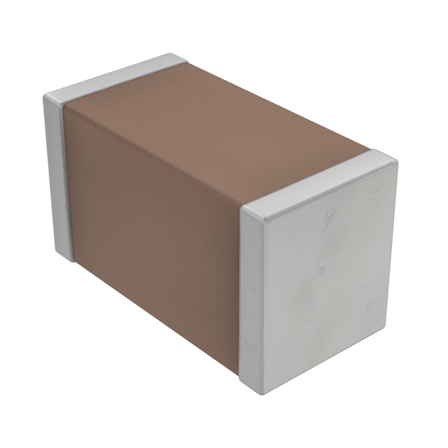
- Passive EMI networks, medical-grade MLCCs (C0G where it matters)
Compute, Time & Memory
- Ultra-low-power MCU (STM32U5/L5-class, MSP430-class) or crossover MCU (i.MX RT-class for benches)
- RTC + 32.768 kHz crystal (DS3231/PCF85xx-class where modules are acceptable)
- Non-volatile memory (W25Q-class QSPI flash) + FRAM (MB85RS-class) for logs and fast writes
Telemetry & Security
- MICS-band transceiver modules (dev only), inductive link ICs, NFC tag/SE (ATECC608A/SE050-class) for secure identity
- Shielded matching networks, SAW/ceramic filters where applicable
Pacing & HV Paths (Fixture-Grade)
- Pacing H-bridge: low-leakage, current-limited driver using medical-grade discrete MOSFETs
- HV charger controllers (LT375x-class) for lab rigs; HV MOSFETs/IGBTs; snubbers; precision dividers for voltage sense
- Bleed resistors and crowbar protection components
Power Management
- Low-IQ LDOs (TPS7A20/ADP7102-class), high-efficiency bucks (TPS62xxx-class)
- Supervisors/reset ICs with sub-µA IQ
- Thermistors (NTC) and digital temp sensors (TMP117-class)
EMC/ESD & Feedthrough
- ESD diodes (PESD5V/RClamp-class), common-mode chokes (DLW-class)
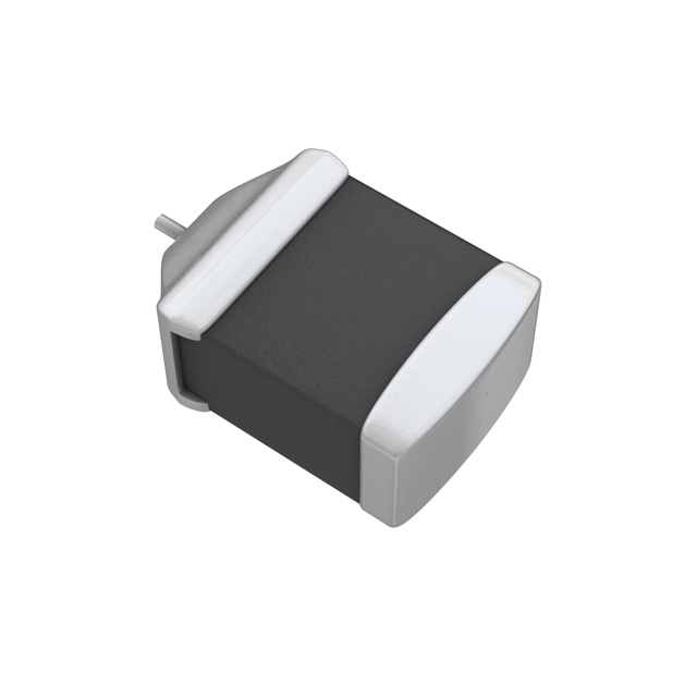
- Hermetic ceramic feedthrough capacitors (implant-qualified suppliers)
15) Field Notes & Failure Modes: The Gremlins That Actually Show Up
- Oversensing: myopotentials, EMI bursts, or lead noise can masquerade as VT. Vector management + morphology correlation + robust blanking reduce false therapies.
- Undersensing: low amplitude signals (scar tissue, lead position) demand careful AFE gain policy and auto-thresholding.
- Lead integrity: micro-fractures show up as intermittent impedance spikes—continuous ICD impedance trending helps.
- Charge aborts: HV charge refused due to thermal or battery state; recover cleanly and log context.
- Aging drift: input offsets, cap ESR, and battery impedance shift slowly—background calibration (within safety bounds) pays dividends.
- Telemetry weirdness: home hubs can be noisy; rate-limit retries; never stall therapy logic waiting for a chatty modem.
.png?x-oss-process=image/auto-orient,1/quality,q_70/format,webp)
16) Glossary (Fast Look-ups)
- ICD — Implantable Cardioverter-Defibrillator.
- ATP — Anti-Tachycardia Pacing.
- VT/VF — Ventricular Tachycardia/Ventricular Fibrillation.
- AFE — Analog Front End (sensing chain).
- CMRR — Common-Mode Rejection Ratio.
- MICS — Medical Implant Communication Service (402–405 MHz).
- CRT-D — Cardiac Resynchronization Therapy Defibrillator.
- FRAM — Ferroelectric RAM (fast, low-power NVM).
- BIST — Built-In Self-Test.
- SBOM — Software Bill of Materials.
Closing (use as CTA)
ERSA Electronics supplies the components and design support that make ICD electronics dependable: ultra-low-noise AFEs and precision ADCs, implant-friendly passives and filters, pacing/HV development fixtures, micro-power PMICs, RTCs and secure elements, MICS/inductive link modules for test, and EMC/ESD protection—plus BOM reviews, cross-brand alternatives, anti-counterfeit QA, and global logistics.
Send your BOM—get cross-parts & lead-time guidance in 24 h.
Related Articles
- ·ICD Electronics: Tiny Lightning, Relentless Reliability
- ·Smart Pill Dispensing Electronics: From Missed Doses to Mission Control
- ·Electrosurgery Electronics: Turning RF Into a Surgical Superpower
- ·Endoscopic Imaging Electronics: Tiny Optics, Big Picture
- ·X-ray & CT Electronics: From Kilovolts to Reconstruction
- ·MRI Core Electronics: From Quench to K-Space
- ·IVD Electronics: Tiny Signals, Big Answers
- ·Vital Signs Monitor Electronics: Tiny Signals, Big Decisions
- ·Neurostimulator Electronics: Tiny Pulses, Big Nerves
- ·Pacemaker Electronics: Tiny Joules, Big Heart







.png?x-oss-process=image/format,webp/resize,h_32)


