
 German
 Japanese
 Portuguese
 Korea
Korea
 Mexico
 Dutch
Dutch


STMicroelectronics
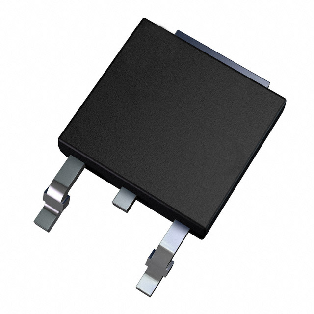
STD60NF55LT4
Why Choose Us?
Professional Platform
B2B & B2C purchasingDelivery at full speed
1-2 days deliveryWide variety
Original manufacturers365 days guarantee
Responsible quality
.png)


Tech Specifications
STD60NF55LT4 Description
The STD60NF55LT4 is a high-power, high-voltage N-channel MOSFET transistor manufactured by STMicroelectronics. It is designed for use in a variety of power electronic applications, including motor control, power supplies, and energy management systems.
Description:
The STD60NF55LT4 is a surface-mount MOSFET transistor with a drain-source voltage (VDS) of 550V and a continuous drain current (ID) of 60A. It has a low on-state resistance (RDS(on)) of 0.04 Ohms, which helps to minimize power dissipation and improve efficiency in power electronic circuits.
Features:
- High-power, high-voltage N-channel MOSFET transistor
- Drain-source voltage (VDS) of 550V
- Continuous drain current (ID) of 60A
- Low on-state resistance (RDS(on)) of 0.04 Ohms
- Surface-mount package for easy integration into power electronic circuits
- Designed for use in a variety of power electronic applications
Applications:
The STD60NF55LT4 is suitable for use in a range of power electronic applications, including:
- Motor control systems for industrial and automotive applications
- Power supplies for telecommunications, computing, and other electronic equipment
- Energy management systems for renewable energy and smart grid applications
- Battery management systems for electric vehicles and energy storage systems
- High-power switching applications in industrial and commercial equipment
Overall, the STD60NF55LT4 is a high-performance MOSFET transistor that offers excellent electrical characteristics and reliability for use in a wide range of power electronic applications. Its low on-state resistance and high power rating make it an ideal choice for applications that require efficient and reliable power switching.
FAQ
Not available to buy online? Want the lower wholesale price? Please Send RFQ to get best price, we will respond immediately


.png?x-oss-process=image/format,webp/resize,h_32)


