
 German
 Japanese
 Portuguese
 Korea
Korea
 Mexico
 Dutch
Dutch


Pulse Oximeter Electronics: LEDs, Photodiodes, AFE & Algorithms

Overview
A Pulse Oximeter (SpO₂) estimates arterial oxygen saturation by measuring the pulsatile absorption of red (~660 nm) and infrared (880–940 nm) light. A typical pulse oximetry system includes high-efficiency LEDs, a large-area photodiode (PD), a low-noise AFE with synchronous detection, and robust algorithms that compute the ratio-of-ratios and gate quality under motion and ambient light.
.png?x-oss-process=image/auto-orient,1/quality,q_70/format,webp)
Architecture
- Emitter: Red & IR LEDs with programmable current pulses (e.g., 5–120 mA, 5–50% duty).
- Detector: Large-area PD; short optical path with mechanical baffling to reduce crosstalk.
- AFE: TIA + ambient subtraction, high-resolution ADC, time-synchronized with LED pulses.
- MCU/DSP: Ratiometric computation, adaptive filtering, quality gating, UI and logging.
- Connectivity (optional): BLE for mobile apps; secure update pipeline.
- Power: Buck/LDO domains for analog, LED rails, and digital; battery charge & gauge.
.png?x-oss-process=image/auto-orient,1/quality,q_70/format,webp)
Optical Subsystem
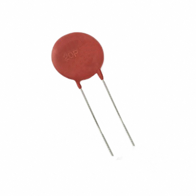
LEDs & Optics
Choose narrow-band red (~660 nm) and IR (880–940 nm) emitters with tight binning. Collimation and a light guide minimize stray paths. Mechanical baffles reduce direct LED→PD leakage.
- Drive: Peak current sized for target SNR at the shortest optical path (finger variety).
- Dimming: Automatic LED current control based on PD DC level to maintain ADC headroom.
- Thermal: Short pulses limit junction heating; monitor LED Vf drift.
.png?x-oss-process=image/auto-orient,1/quality,q_70/format,webp)
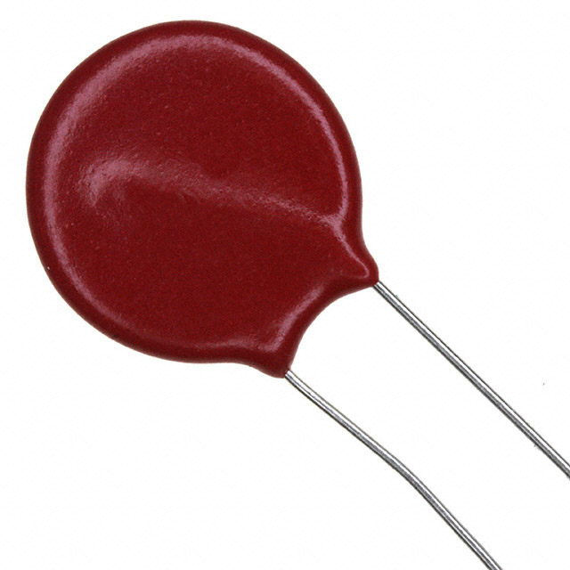
Photodiode & Mechanics
A larger PD improves shot-noise-limited SNR but increases capacitance. Black plastics and gasketed cavities reduce ambient light. Spring force and ergonomics promote consistent perfusion without pressure occlusion.
.png?x-oss-process=image/auto-orient,1/quality,q_70/format,webp)
Analog Front End (AFE)
The AFE converts tiny PD currents into stable samples. Key parameters: input-referred noise, TIA gain range, ADC resolution, ambient-cancel techniques, and precise LED/ADC timing alignment.
- TIA: Programmable gain to keep AC/DC in optimal ADC range; low bias current input stage.
- Ambient subtraction: Sample ambient with LEDs off; subtract digitally or via chopper scheme.
- Sampling: ≥100–200 SPS per color typical; higher rates support motion handling and HRV.
- Shielding: Symmetric layout,
AGND/DGNDstar point, short PD loop area.
.png?x-oss-process=image/auto-orient,1/quality,q_70/format,webp)
Algorithms & Signal Processing
Ratio-of-Ratios
Compute R = (AC/DC)_red / (AC/DC)_IR over beat windows; map R to SpO₂ via calibration curves. DC normalization removes slow trends; AC is extracted with band-pass windows around heart rate.
.png?x-oss-process=image/auto-orient,1/quality,q_70/format,webp)
Motion & Ambient Rejection
- Synchronous sampling with LED chopping and ambient frames.
- Adaptive filtering: LMS/RLS around heart rate; outlier gating on beat shape metrics.
- Sensor fusion: 3-axis accelerometer provides motion masks and quality flags.
- Confidence metrics: perfusion index (PI), signal quality index (SQI), display gating.
.png?x-oss-process=image/auto-orient,1/quality,q_70/format,webp)
Heart Rate & Derived Metrics
Pulse rate derives from inter-beat intervals. Additional metrics (PI, RR trends) are reported only when SQI thresholds are met to prevent misleading readouts.
Power, Safety & EMC
- Domains: Separate analog (AFE), LED rail, and digital/MCU rails; sequence to avoid pops.
- Converters: Use low-ripple DC-DC for LED rail; LDO for AFE reference purity.
- Battery: Charger with JEITA; coulomb gauge for accurate runtime and cycle health.
- Isolation: As required by applied part classification; leak current budgeting.
- EMC: π-filters at LED driver pins; ground guard around PD node; enclosure shielding as needed.
.png?x-oss-process=image/auto-orient,1/quality,q_70/format,webp)
Compliance & Validation
Summarize applicable frameworks (regional requirements vary; this is not medical advice):
- IEC 60601-1 (basic safety/essential performance), IEC 60601-1-2 (EMC).
- ISO 80601-2-61 (pulse oximeter performance—bench and human subject protocols).
- IEC 62304 (software lifecycle), IEC 62366 (usability engineering).
- Risk management: ISO 14971; traceability from hazards → mitigations → verification.
.png?x-oss-process=image/auto-orient,1/quality,q_70/format,webp)
Sample BOM
Representative categories and example families (choose equivalents per availability and cost targets):
- Optical AFE: ADPD-class / AFE44xx-class / MAX8614x-class.
- LED Driver: Programmable current pulse driver with fast settling and diagnostics.
- Photodiode: Large-area, low dark current, low capacitance device with black package.
- MCU: Low-power Cortex-M with DSP/SIMD and BLE option if needed.
- Power: LED buck, AFE LDO (low noise), system PMIC/charger and fuel gauge.
- Passives/EMC: π-filters, RC snubbers, ferrite beads, precision resistors (0.1–0.5%).
- Sensors (optional): 3-axis accelerometer for motion rejection; skin temp for correction.
.png?x-oss-process=image/auto-orient,1/quality,q_70/format,webp)
Disclaimer: This page describes electronics design aspects only and does not provide medical advice or performance claims. Regional regulations may differ.

Related Articles
- ·ICD Electronics: Tiny Lightning, Relentless Reliability
- ·Smart Pill Dispensing Electronics: From Missed Doses to Mission Control
- ·Electrosurgery Electronics: Turning RF Into a Surgical Superpower
- ·Endoscopic Imaging Electronics: Tiny Optics, Big Picture
- ·X-ray & CT Electronics: From Kilovolts to Reconstruction
- ·MRI Core Electronics: From Quench to K-Space
- ·IVD Electronics: Tiny Signals, Big Answers
- ·Vital Signs Monitor Electronics: Tiny Signals, Big Decisions
- ·Neurostimulator Electronics: Tiny Pulses, Big Nerves
- ·Pacemaker Electronics: Tiny Joules, Big Heart
 FAQ
FAQ


.png?x-oss-process=image/format,webp/resize,h_32)


