
STMicroelectronics
STP170N8F7

Why Choose Us?
Professional Platform
B2B & B2C purchasingDelivery at full speed
1-2 days deliveryWide variety
Original manufacturers365 days guarantee
Responsible quality
.png)


Tech Specifications
STP170N8F7 Description
STP170N8F7 Description
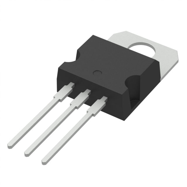
The STP170N8F7 from STMicroelectronics is an N-channel 80V, 120A power MOSFET housed in a TO-220 package, designed for high-efficiency power switching applications. Part of the STripFET™ F7 series, it leverages advanced Metal Oxide Semiconductor (MOSFET) technology to deliver low on-resistance (3.9mΩ @ 60A, 10V) and high current-handling capability. With a 250W (Tc) maximum power dissipation and a ±20V gate-source voltage rating, this device is optimized for robust performance in demanding environments. Although marked as Obsolete, it remains a reliable choice for legacy designs due to its ROHS3 compliance and REACH unaffected status.
STP170N8F7 Features
- Low Rds(On): 3.9mΩ minimizes conduction losses, enhancing efficiency in high-current applications.
- High Current Rating: 120A (Tc) continuous drain current supports heavy-load conditions.
- Fast Switching: Low gate charge (120nC @ 10V) and input capacitance (8710pF @ 40V) ensure rapid switching transitions.
- Thermal Performance: TO-220 package with 250W (Tc) dissipation capability for effective heat management.
- Wide Vgs Range: ±20V gate drive tolerance provides flexibility in drive circuit design.
- Reliability: MSL 1 (Unlimited) moisture sensitivity and EAR99 ECCN classification for broad industrial use.
STP170N8F7 Applications
Ideal for:
- DC-DC Converters: Low Rds(On) and high current capability optimize power conversion efficiency.
- Motor Drives: Robust performance in H-bridge and inverter configurations for industrial motors.
- Power Supplies: Suitable for SMPS and UPS systems requiring high switching efficiency.
- Automotive Systems: Legacy designs in battery management and load switching (though newer alternatives may be preferred).
- Industrial Switching: High-reliability applications like solenoid drivers and relay replacements.
Conclusion of STP170N8F7
The STP170N8F7 excels in high-power, high-efficiency applications with its low on-resistance, high current capacity, and thermal resilience. While obsolete, its STripFET™ F7 technology ensures it remains competitive in legacy systems. Engineers valuing low conduction losses and fast switching in TO-220 packages may still find it suitable for industrial, automotive, and power conversion designs. For new projects, consider STMicroelectronics' updated offerings with similar or improved specs.
FAQ
| Quantity | Unit Price | Ext. Price |
|---|---|---|
| 1+ | $2.37085 | $2.37 |
| 10+ | $2.00057 | $20.01 |
| 50+ | $1.76915 | $88.46 |
Not available to buy online? Want the lower wholesale price? Please Send RFQ to get best price, we will respond immediately


.png?x-oss-process=image/format,webp/resize,h_32)


