
 German
 Japanese
 Portuguese
 Korea
Korea
 Mexico
 Dutch
Dutch


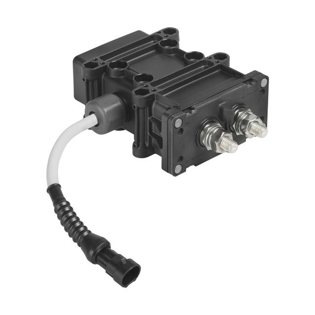
Automotive Domain Controller: Architecture, Functions, and Key IC Selection

What is an Automotive Domain Controller?
An automotive domain controller is a centralized computing unit designed to manage a specific vehicle domain—such as ADAS, powertrain, body electronics, or infotainment. Compared with a traditional distributed ECU layout, a domain controller adopts a centralized architecture to reduce wiring complexity, improve compute density, and lower total system cost. It is a foundational automotive computing unit for software-defined vehicles (SDV).

Evolution of Vehicle Electronic Architecture
From distributed ECUs to domain controllers, then zonal controllers, and ultimately to a central computing platform.
In short, a vehicle domain controller sits at the heart of a centralized architecture, acting as the primary automotive computing unit for each domain while enabling scalable software and hardware evolution.
Why the Automotive Industry is Moving to Domain Controllers
Modern vehicles are transitioning from distributed ECUs to domain controllers as part of a centralized architecture. The shift is driven by wiring and cost pressure, higher compute needs, and the rise of software-defined vehicles (SDV) with OTA capabilities and robust functional safety requirements (ISO 26262, ASIL-B/D).
Key Drivers
- Cabling reduction & weight savings: shorter harnesses and fewer connectors reduce complexity and mass.
- Lower power consumption: consolidated compute and optimized power domains improve efficiency.
- Cost optimization: fewer ECUs, simplified wiring, and shared compute lower total system cost (TCO).
- OTA software updates (SDV): centralized platforms enable reliable over-the-air updates and faster feature rollout.
- Functional safety (ISO 26262): easier to implement ASIL-B/D safety concepts, diagnostics, and redundancy at the domain level.
Distributed ECUs vs. Domain Controller Architecture

| Aspect | Distributed ECUs | Domain Controller |
|---|---|---|
| Wiring & Cabling | Long harnesses across vehicle; many connectors. | Shorter harnesses inside domains; fewer connectors. |
| Compute | Scattered low/mid-range MCUs per function. | Consolidated high-performance MCU/SoC per domain. |
| Power & Efficiency | Multiple isolated power islands; higher idle losses. | Shared power rails; coordinated low-power modes. |
| Software & OTA | Fragmented updates; workshop visits common. | Centralized OTA, faster rollout, SDV-ready. |
| Functional Safety | Safety per ECU; complex cross-ECU coordination. | Domain-level ASIL concepts, diagnostics, redundancy. |
| Total Cost | Many ECUs + long harness = higher TCO. | Fewer ECUs + simplified wiring = lower TCO. |

Types of Automotive Domain Controllers
Automotive domain controllers are specialized computing units designed to handle different functional domains in a vehicle’s centralized architecture. Each type is optimized for specific subsystems, ensuring high performance, functional safety, and efficient communication.
ADAS Domain Controller
The ADAS controller processes data from cameras, radar, and LiDAR sensors to enable advanced driver assistance and autonomous driving functions. It requires high-performance SoCs capable of handling massive parallel processing with low latency.
- Main Functions: Sensor fusion, object detection, lane keeping, adaptive cruise control
- Core IC Examples: NXP S32G, Renesas R-Car H3, TI TDA4VM
- Typical Interfaces: MIPI CSI, Ethernet AVB, CAN FD
Body Domain Controller
The body controller manages interior and exterior comfort systems such as lighting, windows, mirrors, and seat control. These controllers prioritize real-time responsiveness and robustness.
- Main Functions: Lighting control, HVAC, central locking
- Core IC Examples: Microchip PIC32MZ, ST SPC58, NXP S12ZVC
- Typical Interfaces: CAN, LIN, FlexRay
Powertrain Domain Controller
The powertrain controller supervises engine, transmission, and electric drive systems. These units demand ICs with high thermal tolerance and real-time deterministic control.
- Main Functions: Engine control, EV motor management, regenerative braking
- Core IC Examples: Infineon AURIX TC3xx, Renesas RH850, NXP MPC5777C
- Typical Interfaces: SENT, CAN FD, PSI5
Infotainment / IVI Domain Controller
The IVI controller handles multimedia playback, navigation, and connected services. High-performance GPUs and audio/video interface chips are key in this domain.
- Main Functions: Multimedia streaming, navigation, smartphone integration
- Core IC Examples: Qualcomm Snapdragon SA8155P, Renesas R-Car M3, TI Jacinto 7
- Typical Interfaces: HDMI, USB, MOST, Ethernet AVB

System Architecture & Block Diagram
An automotive domain controller integrates multiple hardware modules into a single, centralized computing unit to process data, manage power, and communicate with other vehicle systems. The following architecture illustrates the main functional blocks commonly found in a modern domain controller.
Key Modules
- SoC (System-on-Chip): High-performance multi-core processors (e.g., ARM Cortex-A/R cores) with integrated GPU/DSP units for intensive computing tasks such as sensor fusion, image processing, and AI inference.
- PMIC (Power Management IC): Regulates and distributes power to different subsystems, ensuring efficiency and thermal stability under automotive-grade conditions (AEC-Q100 compliance).
- Memory: High-speed DRAM (LPDDR4/LPDDR5) for runtime processing and non-volatile storage (e.g., eMMC, UFS) for software and firmware.
- Communication Interfaces: Ethernet PHY (1000BASE-T1/10GBASE-T1), CAN FD, FlexRay, and PCIe for high-speed, low-latency data transfer between in-vehicle networks.
- Security Module: Hardware security modules (HSM) for encryption, secure boot, and secure key storage to meet cybersecurity requirements (ISO/SAE 21434).
- Sensor/Actuator Interfaces: Dedicated ADC/DAC channels, LIN transceivers, and GPIO expanders for direct integration with sensors and actuators.
Engineering Role of Each Module
The SoC acts as the brain, executing application and middleware tasks. The PMIC ensures stable voltage supply, protecting against fluctuations from the vehicle’s 12V/48V system. Memory modules provide both temporary and permanent storage, critical for processing large data streams such as ADAS camera feeds. Communication interfaces bridge the domain controller with other ECUs and sensors, while the security module safeguards data integrity and access. Sensor/actuator interfaces enable real-time control and monitoring of vehicle subsystems.

5. Key IC Selection from Leading Brands
Selecting the right integrated circuits (ICs) is critical for building a reliable and high-performance automotive domain controller. The following table outlines key IC categories, representative models from leading automotive semiconductor brands, and their notable specifications.

| Function | Example ICs | Brand | Key Specs |
|---|---|---|---|
| Automotive SoC | S32G2 | NXP | Quad-core ARM Cortex-A53, ASIL-D, High-speed networking |
| PMIC (Power Management IC) | TPS650330-Q1 | Texas Instruments | 3x DC/DC converters, ASIL-B, 3.3V/5V outputs |
| Ethernet PHY | DP83TG720S-Q1 | Texas Instruments | 1000BASE-T1, ASIL-B, Low power mode |
| MCU (Microcontroller) | RH850/P1X | Renesas | Dual lockstep CPU, ISO 26262, CAN FD interface |
| CAN Transceiver | TJA1044GT | NXP | High-speed CAN FD, Low-power standby, EMC optimized |
Engineering Notes:
- Automotive SoC: Acts as the computational brain for high-speed data processing and control algorithms.
- PMIC: Ensures stable power delivery to all sub-modules with automotive-grade safety features.
- Ethernet PHY: Enables gigabit communication between sensors, ECUs, and the domain controller.
- MCU: Handles deterministic control tasks, often in safety-critical loops.
- CAN Transceiver: Maintains robust communication across the vehicle’s CAN FD network.
Challenges and Design Considerations
Building an automotive domain controller is more than selecting high-performance ICs. The platform must meet stringent functional safety, thermal, power, and communications requirements while supporting OTA updates and cybersecurity in harsh automotive environments.
6.1 Functional Safety (ISO 26262)
- ASIL targets: Typical objectives are ASIL-B to ASIL-D depending on the domain (e.g., ADAS often ASIL-D).
- Lockstep / redundant compute: Dual-core lockstep MCUs or hot/cold redundant paths detect latent faults.
- Safety mechanisms: Safe state handling, watchdogs, ECC on memories, end-to-end communication protection.
- FMEDA & safety case: Quantified metrics (SPFM, LFM, PMHF) and a documented safety case are required.
6.2 Thermal Management
- Hot spots: Multi-core SoCs and high-speed PHYs can exceed 10–20 W; junction temperatures must be controlled.
- Mitigations: Heat spreaders, vapor chambers, active airflow or liquid cooling for ADAS; high-copper PCBs and via farms.
- Design tips: Place PMICs/inductors away from memory; define keep-outs above SoC for heatsink fasteners.
6.3 Power Supply & PMIC Design
- Multiple rails: 0.8–1.2 V core, 1.1/1.8 V I/O, 3.3/5 V peripherals; strict power-up/down sequencing.
- Crank & transients: Must ride through cold crank, load dump, surge and reverse battery per OEM specs.
- Monitoring: PMIC with OV/UV/OC protections, voltage monitors, watchdog, and fail-safe rails for safety MCU.
- EMI: Spread-spectrum switching, synchronized converters, LC filters near high-di/dt loads.
6.4 Communication Interfaces & EMC
- High-speed backbone: Ethernet PHY (100/1000BASE-T1, moving to multi-gig), PCIe to external accelerators.
- Legacy networks: CAN FD, LIN, FlexRay must coexist; use isolation where required.
- Signal integrity: Length-matched differential pairs, impedance control, AC coupling placement, common-mode chokes.
- EMC compliance: Proper filtering, stitching vias, and segmentation of noisy/power sections from sensitive analog.
6.5 Software, OTA & Cybersecurity
- OTA readiness: A/B partitions, rollback strategy, delta updates; minimize downtime for safety-critical domains.
- Secure boot & keys: Hardware HSM, immutable root of trust, encrypted storage, authenticated updates.
- Standards: ISO/SAE 21434 for cybersecurity; AUTOSAR Classic/Adaptive or POSIX Linux for software stack.
- Interfaces: Ethernet PHY, CAN FD, FlexRay, PCIe, MIPI CSI/DSI.
- Power: PMIC with sequencing, watchdog, fail-safe LDO for safety MCU; pre-compliance EMI checks early.

Frequently Asked Questions
What is the function of a domain controller in a car?
A domain controller in automotive centralizes computing for specific vehicle domains such as ADAS, body, powertrain, or infotainment. It manages data processing, communication, and control tasks within that domain, improving efficiency, reducing wiring, and enabling advanced features like OTA updates.
What is a domain controller in automotive?
In the automotive industry, a domain controller (DCU) is a high-performance electronic control unit designed to manage a set of related functions within a specific domain, replacing multiple distributed ECUs with a centralized computing platform.
What is DCU in automotive?
DCU stands for Domain Control Unit in automotive applications. It serves as the computing hub for one or more functional domains, such as ADAS, infotainment, or chassis systems, integrating sensors, actuators, and network communications.
What is the difference between ECU and DCU?
An ECU (Electronic Control Unit) is typically responsible for a single function, while a DCU (Domain Control Unit) consolidates multiple related functions within a specific domain. This reduces wiring complexity, cost, and improves processing capability.
What chips are used in domain controllers?
Domain controllers use a combination of high-performance SoCs, MCUs, PMICs, Ethernet PHYs, and communication interface chips such as CAN FD or FlexRay. Brands like NXP, Renesas, TI, and ST offer automotive-grade solutions.
What is the role of a domain controller?
The role of a domain controller is to centralize computing and decision-making for a vehicle's domain, manage communication between subsystems, process sensor data, and execute control algorithms in real time.
What is an ADAS domain controller?
An ADAS domain controller processes data from cameras, radars, and LiDAR sensors to support advanced driver assistance functions such as lane keeping, adaptive cruise control, and emergency braking.
What is DCU in Toyota?
In Toyota vehicles, a DCU refers to a Domain Control Unit that manages specific vehicle functions, often related to infotainment, navigation, or safety systems, depending on the model and configuration.
What is a DCU module?
A DCU module is the hardware assembly containing the domain controller’s processing unit, memory, power management, and communication interfaces, packaged for integration into the vehicle’s electronic architecture.
What does DCU stand for in cars?
In cars, DCU stands for Domain Control Unit, the centralized ECU responsible for controlling and managing functions within a specific domain.
BOM & Quote Support for Domain Controller Projects
Working on an automotive domain controller design and need help with IC selection? Our engineering team can review your BOM (Bill of Materials) and recommend the most suitable automotive-grade chips from leading brands like Texas Instruments, NXP, Renesas, STMicroelectronics, onsemi, Microchip, and Melexis.
Submit Your BOM for IC Matching & Quote
- ✔️ Engineering review of your design requirements
- ✔️ Recommend equivalent or drop-in replacement ICs
- ✔️ Provide price & lead time based on your demand
Need to explore parts yourself? Visit our Automotive IC Catalog for SoCs, PMICs, MCUs, Ethernet PHYs, and more used in vehicle domain controllers.

Related Articles
- ·Memory Chip Complete Guide: Definition, Manufacturers, Shortage, Manufacturing Process and Working Principles
- ·Fiber Optic Switch Guide: Definition, Connection Methods, Cabling, Disconnection and FAQ
- ·Optical Fiber Transmitter and Receiver Guide
- ·ICD Driver, LCD Driver & LCD Panel Driver Board Guide
- ·Touch Screen Overlay Guide for Commercial & Industrial Applications
- ·Cold Cathode Fluorescent Lamp Guide
- ·Complete Buying Guide for LED Video Walls & Commercial LED Displays
- ·The Complete Guide to Diode Lasers
- ·LED Emitter Guide: Definition, Brightness, Beam Angle, Soldering, Flashlight Upgrade, IR Usage and Grounding
- ·Inrush Current Limiter: Working Principle, Calculation, Selection Guide, and Motor / Capacitor Applications


.png?x-oss-process=image/format,webp/resize,h_32)


