
 German
 Japanese
 Portuguese
 Korea
Korea
 Mexico
 Dutch
Dutch


Power Management Systems: Types, Architecture, IC Selection, and Troubleshooting

What Is a Power Management System?
A power management system converts, distributes, protects, monitors and sequences energy from an input source to multiple regulated rails.
In practice: Input → Conversion/Regulation → Distribution/Protection → Monitoring/Control → Storage/EMI/Thermal.

Industry baseline: IC share by count ≈ 5–20%; by cost ≈ 20–40%. Magnetics and power FETs often dominate volume and cost.
Power management is system engineering—not a single chip. Real designs are multi-dimensional (types A–H can overlap). This guide shows how to architect, select, and validate reliable multi-rail power.
Core Components of a Power Management System
The building blocks you’ll actually choose and validate: conversion/regulation, distribution/protection, monitoring/control, and energy & EMI/thermal. Each block includes what it does, key parameters, quick selection rules, common pitfalls, validation checks, and representative series (cross-brand).
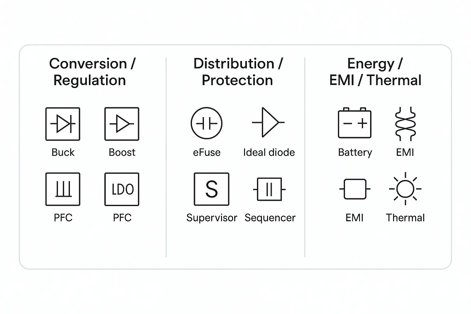
A) Conversion & Regulation
Buck / Boost / Buck-Boost / SEPIC / Flyback / LLC, LDO, PFC, and integrated power modules (with inductor). Convert the input to target rails while meeting efficiency, ripple, transient and size goals.
- Vin range, Vout & Iout (avg/peak), efficiency target
- Ripple/noise, transient ΔV/ΔI, switching freq., sync rect., spread-spectrum, Iq
- Soft-start, PG, thermals (RθJA), package height
- LDO: dropout, PSRR vs. freq, noise density, stability (ESR/load)
- Flyback/LLC: transformer spec, isolation, SR drive, core loss
- PFC: PF/THD, efficiency window, EMI margin
- High current/efficiency → sync Buck; >30 A → multiphase
- Wide input / automotive → Buck-Boost/SEPIC + eFuse/Hot-Swap
- RF/clock/sensor → Switcher + LDO two-stage to lower noise
- AC low/mid power → Flyback; higher efficiency → LLC
- Schedule/space tight → Power Module (predictable EMI/thermal)
- Regulatory >75 W → add PFC and system-level EMI plan
- Poor compensation → ringing/instability on load steps
- Output cap ESR/ESL not per datasheet → ripple/transient issues
- Large HF loop areas → EMI failures
- LDO dropout/power not budgeted → thermal overload
- Flyback transformer guessed → loss/temperature/insulation risk
- Bode/phase margin (or equivalent)
- 10–90% load step waveforms; cold/soft-start profiles
- Ripple with correct probing; efficiency curves
- Thermal map; EMI pre-scan (conducted/radiated)
Buck/Boost/ctrl: TI LM/TPS; ST L798/L698; onsemi NCP/NCV; Renesas ISL/RAA; Microchip MIC/MPM; NXP TEA (AC front).
LDO: TI TPS7A/TLV; ST LD; Renesas ISL/MIC; Microchip MCP/TC; onsemi NCP/NCV.
Flyback/LLC/PFC: ST VIPer/L656x/L6599; TI UCC; onsemi NCP/NDL; Renesas RAA/ISL; NXP TEA.
Modules (with inductor): TI TPSM; Microchip MPM; Renesas RAA modules; onsemi integrated options.
B) Distribution & Protection
Load switches, ideal-diode OR-ing, Power MUX, hot-swap controllers, eFuse, and TVS/ESD. Manage power paths, soft-start, limits and fault handling with event flags.
- Voltage/current rating, RDS(on), Ilim mode (CC/hiccup/off)
- Short-circuit response time, soft-start time
- Reverse blocking, OV/UV thresholds, thermal shutdown
- Surge capability, PG/FAULT pins
- No-loss OR-ing → ideal-diode controller (w/ or w/o FETs)
- Multi-source (USB/adapter/battery) → Power MUX w/ priority + reverse protection
- Hot-plug backplane → Hot-Swap controller
- Granular protection → eFuse (configurable limits, events)
- Front-end surge/ESD → TVS close to connector, short ground return
- Ignore short-circuit speed → copper damage before trip
- Miss reverse blocking → backfeed destroys upstream
- MUX priority wrong vs. system intent
- TVS ground path too long → ineffective clamp
- Test: short-circuit shots, soft-start profiles, reverse tests, plug/unplug, FAULT/PG logging, thermal map
eFuse/Hot-Swap: TI TPS259x/UCC; Renesas RAA/ISL; onsemi FPF/NCV; ST eFuses; Microchip MIC.
Ideal-diode/OR-ing: TI LM/ideal-diode; Renesas/ISL; onsemi solutions.
Power MUX: TI TPS/TMUX power-path; Renesas/Maxim; Microchip power-path ICs.
C) Monitoring & Control
Current/voltage/power monitors, supervisors/reset, power sequencers, and digital power via PMBus/SMBus/UART. Essential for production consistency, telemetry and fast field diagnostics.
- Range/resolution, common-mode window, shunt vs. Hall vs. isolated
- Bandwidth/SR, accuracy/drift, alert latency, interface/addressing
- Supervisor thresholds/delay; reset hold; watchdog
- Sequencer rails, dependencies, PG compatibility
- Servers/FPGA → prefer PMBus + telemetry/logging
- Low-voltage precision → shunt amplifiers; isolate when needed
- Multi-rail → dedicated sequencer + unified PG polarity
- Shunt too large → heat/efficiency loss; too small → noise/precision loss
- Bandwidth < load-step dynamics → false alarms/missed events
- Temp-sweep offset/gain calibration
- Full-scale & small-signal error vs. spec
- PG/RESET timing capture; injected OV/UV/OCP/OTP tests
- Log readout & fault correlation
Monitors: TI INA/INA2xx; Microchip PAC1xxx; Renesas ZL/ISL (incl. digital power); Melexis MLX912xx (Hall).
Supervisors/Sequencers: TI TPS/LM; Renesas ISL/RAA; Microchip MIC/TC; onsemi NCP.
Digital power (PMBus): Renesas RAA/ZL; TI UCD/TPS digital; onsemi NCP digital.
D) Energy & EMI / Thermal
Batteries and supercaps for buffering and peak sharing; magnetics and EMI filters decide efficiency/EMI outcomes; temperature sensing and fan drivers close the thermal loop.
- Battery chemistry/cells, charge/discharge currents, protection & balancing
- Supercap C & ESR; inductor Isat/DCR/loss
- CM/DM chokes, filter targets; temp sensor accuracy/response
- Fan control modes (PWM/Tach), acoustics vs. cooling
- Peak handling → battery + supercap (with pre-charge/balance)
- EMI: shrink HF loops first; add filters later; use spread-spectrum if needed
- Hotspots usually FETs/magnetics → design copper/planes for heat spreading
- Inductor Isat (not only rated current) is critical
- Mixed CM/DM filters with poor grounds → worse EMI
- Peak/pulse load tests; hold-up time
- EMI pre-compliance (conducted/radiated)
- Thermal rise and heat-spreading path verification
Battery/charge/AFE: TI BQ; Microchip MCP738xx; Renesas ISL942xx; NXP AFE.
Temp/fan: TI / onsemi / Microchip temperature ICs and FAN drivers.
Magnetics/filters: link to your magnetics/EMI selection pages for deeper guidance.
Two-Stage Recipe: Switching Regulator + LDO
A pragmatic balance of efficiency and noise. Use a high-efficiency switcher to drop the bulk of voltage/current, then a low-noise LDO to clean up ripple for sensitive analog/RF/clock loads.
- LDO headroom (VIN − VOUT) & power dissipation
- PSRR at target frequencies (e.g., ~1 MHz)
- Output cap type/ESR per datasheet; stability across load/temp
- Sync Buck (spread-spectrum) → low-noise LDO → sensor/clock/ADC driver
- Automotive: Buck-Boost (wide Vin) → AEC-Q LDO → camera/radar analog front-end
- A: TI TPS62xxx + TPS7Axx; + Microchip MCP738xx (charger, optional)
- B: ST L798/L698 + LD-series LDO; + Renesas ISL/RAA monitors
- C: onsemi NCV Buck + NCP LDO; + Melexis MLX sensors (temp/current)
Types of Power Management Systems (Multi-Dimensional A–H)
Power management “types” are multi-dimensional. One design may belong to several categories at once. Pick a primary dimension based on your top constraints (safety/EMI, noise/efficiency, time-to-market/footprint, redundancy, etc.), then refine with secondary tags.

Type A — Input & Isolation (AC→DC / DC→DC)
Classify by input form and isolation. AC fronts involve PFC & safety; industrial/communications often use isolated DC/DC.
- Scenarios: AC adapters (isolated), 24 V→logic (isolated/non-isolated), 12 V vehicle rails.
- Keys: Vin range & surges, insulation/creepage, efficiency/thermal/EMI, PF/THD.
- Decide: human safety/long cables → isolated; compact board → non-isolated; AC > 75 W → PFC + isolated.
- Test: safety review, hi-pot, CISPR (conducted/radiated), surge/sag/interrupt.
Type B — Regulation (LDO vs SMPS)
Classify by regulation method: linear LDO (low noise) vs. switching SMPS (high efficiency & density).
- Scenarios: RF/clock/sensors (LDO or 2-stage); high-current loads (SMPS/multiphase).
- Keys: PSRR, noise density, dropout, efficiency, frequency, sync rect., spread-spectrum, Iq.
- Decide: ultra-low noise → LDO; mid/high current → sync Buck; RF → Switcher + LDO.
- Test: PSRR vs. freq, load-step, noise, EMI pre-scan.
Type C — System Architecture (Discrete / PMIC / Module)
Classify by solution form: discrete controller+FET, integrated PMIC, or inductor-in module.
- Scenarios: custom high-power (discrete); SoC/FPGA multi-rail (PMIC); fast TTM/small board (module).
- Keys: BOM/area/height, thermal/efficiency, sequencing/telemetry, development time.
- Decide: differentiation → discrete; multi-rail SoC → PMIC; tight schedule/space → module.
- Test: power-up sequencing, thermal map, efficiency, EMI.
Type D — Distribution & Power Path (POL / MUX / OR-ing / Hot-Swap / eFuse)
Manage source selection, soft-start, protection, and fault logging between source and loads.
- Scenarios: multi-source (USB/adapter/battery), redundancy OR-ing, backplane hot-plug, granular protection.
- Keys: RDS(on), Ilim mode/speed, reverse blocking, OV/UV, thermal, PG/FAULT.
- Decide: low-loss redundancy → ideal-diode OR-ing; multi-source → Power MUX; plug events → Hot-Swap; fine protection → eFuse.
- Test: short-circuit shots, plug/unplug, reverse tests, FAULT/PG capture.
Type E — Battery & Energy Harvesting
Storage-centric systems: charger, protection/BMS, fuel-gauge, supercap buffering, and micro-energy harvesting.
- Scenarios: wearables/IoT, handhelds, AGV/backup, peak sharing via supercaps.
- Keys: chemistry/cell count, charge/discharge, protection thresholds, balancing, gauge model, cold-start, Iq.
- Decide: single/multi-cell → proper charger/BMS/AFE; high peaks → supercap + pre-charge; micro-energy → harvester IC + ultra-low Iq.
- Test: charge profile & temp sweep, capacity learning, pulse/hold-up, cycle life.
Type F — Control Mode (Analog vs Digital: PMBus/SMBus/Telemetry)
Choose how rails are controlled and observed: analog for simplicity/cost, digital for telemetry, logging and remote config.
- Scenarios: servers/base-stations/FPGA (heavy telemetry), one-time factory programming.
- Keys: PMBus commands, telemetry accuracy/bandwidth, NVM config, fault log fields, bus topology.
- Decide: need ops/logging → digital power; few rails/cost-sensitive → analog.
- Test: register scripts, NVM verify, fault injection, population consistency.
Type G — Application Domain (Automotive / Industrial / Compute & Comms / Consumer & IoT)
Classify by industry environment and regulations.
- Automotive: load-dump/reverse, wide temp, AEC-Q100, CISPR; camera/radar/ECU.
- Industrial: isolation, redundancy OR-ing, 24 V bus, EMC.
- Compute/Comms: multiphase Buck, DVS, tight ripple/transient, rich telemetry.
- Consumer/IoT: ultra-low Iq, compact chargers, cost.
- Test: CISPR/ESD/surge per domain, DVS/transients, lifetime drift.
Type H — Redundancy & Reliability (Single / Dual-Source OR-ing / Black-Start / Sequencing / Watchdog)
Classify by fault coverage and uptime goals: redundancy, black-start capability, and robust PG/reset/watchdog chains.
- Scenarios: servers/telecom/industrial control/vehicles; black-start and strict brown-out.
- Keys: coverage/MTBF/MTTR, OR-ing losses, black-start constraints, PG/RESET chain, watchdog, logs.
- Decide: high downtime cost → dual-source + OR-ing + Hot-Swap + telemetry; black-start → pre-charge/soft-start/sequencing.
- Test: switchover latency, backfeed tests, black-start sequence, fault injection & recovery, event traceability.
- Automotive camera: A(DC/DC non-isolated) · B(SMPS+LDO) · C(PMIC) · D(MUX+eFuse) · G(Automotive) · H(PG/sequence)
- Industrial PLC: A(Isolated DC/DC) · B(SMPS) · C(Discrete) · D(OR-ing+eFuse) · F(Partial digital) · G(Industrial) · H(Redundancy)
- FPGA board: A(Board-level DC/DC) · B(Multiphase+LDO) · C(PMIC+Discrete) · D(POL) · F(PMBus) · G(Compute/Comms)
Architecting Multi-Rail Power Trees
A practical, step-by-step method to go from requirements to a validated multi-rail design: define rails and priorities, plan sequencing and reset, meet ripple/transient targets with stable compensation, place high-current POL near the load, integrate DVS/AVS for SoC/FPGA, and co-review thermal & EMI early.

4.1 Define Rails (Worksheet)
Capture rail specs once to drive architecture and verification. Use the fields below as your canonical worksheet.
- Rail name (e.g., VCORE/VDDQ/VPP/VIO/AVDD)
- Nominal V & tolerance (±%)
- Iavg / Ipeak & peak duration
- Load type (digital/analog/RF/IO)
- Ripple/noise target (mVpp, bandwidth)
- Power-up/down priority (↑/↓)
- PG dependencies (who unlocks whom)
- Reset hold (ms) and release conditions
- Brown-out response
- DVS range, step, slew (mV/μs)
- Interface (VID/PMBus/I²C/SVID)
- OV/UV thresholds, retry vs. latch-off
- Event logging fields
4.2 Sequencing & Reset Strategy
- Power-up: core → memory/aux → IO → analog PLL
- Power-down: reverse order; ensure safe discharge paths
- Normalize PG polarity/levels to avoid logic ambiguity
- Release RESET only after all critical rails are stable
- Capture EN/SW/Vout/PG/RESET multi-channel timing
- Verify brown-out behavior & retry/latch policy
- Log PG violations and correlation to loads
4.3 Ripple & Transient Targets + Stable Compensation
- Transient estimate: ΔV ≈ ΔI·ESR + (ΔI·Δt)/C
- Loop bandwidth target: ~ fSW / 10–20
- Phase margin ≥ 45–60°, gain margin ≥ 8–10 dB
- Mix ceramics + higher-ESR caps for damping
- Short ground spring; bandwidth-limited scope
- Kelvin sense for ripple; avoid long ground leads
- Probe at load point for worst-case excursions
4.4 Point-of-Load (POL) Placement & Loop Area Minimization
- Place high-current POL close to loads; minimize IR drop and loop area
- Shrink HF current loops (VIN bypass, SW, rectification)
- Use Kelvin feedback; partition analog/digital grounds with single-point tie
- Interleave phases for ripple/EMI reduction on adjacent rails
- Plan heat spreading (copper, vias, airflow, shields)
4.5 DVS/AVS for SoC/FPGA
- VID/PMBus/I²C/SVID per platform
- Define step size and slew (mV/μs) to avoid surge current
- Coordinate with P-states/clock domains
- Load-line (droop) to trade transient vs. static margin
- Safe fallback voltage if DVS command fails
- Timeouts, retries, and logging
4.6 Thermal & EMI Co-Review
- Multiphase Buck sizing & interleaving to reduce ripple peaks
- Switching frequency trade-offs (size vs. switching loss)
- Spread-spectrum, RC snubbers, ferrite beads + LC filters
- Filter placement: short returns; CM/DM choke roles; Y-cap positions
- Near-field probe scans for hotspots/noise sources
- Conducted/radiated EMI pre-scan before freeze
- Thermal mapping across VIN/Iout/ambient corners
4.7 Verification Plan & Acceptance Criteria
- Efficiency @ 25/50/75/100% load; ripple; 10–90% steps
- Cold/soft-start, hold-up time, VIN min/max
- Thermal rise at worst-case corners
- EN→PG→RESET order and windows (up/down)
- OV/UV/OCP/OTP behavior, reverse blocking/backfeed
- EMI (conducted/radiated) pre-scan; ESD/surge as applicable
- PMBus/SMBus telemetry readout and limits
- Address conflicts; NVM configuration verify
- Fault injection and event traceability
4.8 Example Power Trees (Copy-Ready)
- Input 12 V → multiphase Buck VCORE 0.85 V @ 40 A (VID/DVS, load-line)
- VDDQ 1.2 V @ 6 A; VPP 2.5 V @ 0.5 A (switcher+LDO)
- VIO 3.3 V @ 3 A; VDDPLL 1.8 V @ 0.3 A (switcher+LDO)
- Order: VCORE → VDDQ/VPP → VIO → VDDPLL; RESET +10–20 ms
- Front-end eFuse + MUX; PG to sequencer
- 12 V vehicle → eFuse/Hot-Swap → Buck-Boost → rails
- 3.3 V logic / 1.8 V ISP / 2.8 V AVDD (switcher+LDO)
- Order: AVDD stable → enable ISP → IO last; reverse for shutdown
- TVS near connector; CM/DM chokes; shield grounding; AEC-Q LDO
PMIC vs. Discrete vs. Module — Comparison & Decision
Choose a solution form using engineering criteria: BOM cost, area/height, efficiency, ripple/noise, thermal, EMI, sequencing/telemetry/maintainability, mass-production consistency, and time-to-market. Use the quick summary below, then the comparison table and decision tree to narrow your path.

PMIC
Multi-rail integration with sequencing, DVS, and telemetry. Great for SoC/FPGA; fewer externals, faster consistency. Trade-off: voltage/pin options can limit flexibility; hotspot near chip.
Discrete
Highest flexibility and scalable thermals (e.g., multiphase). Best for high power or differentiation. Trade-off: higher BOM and debug cost, more EMI uncertainty, longer tuning to reach consistency.
Module
Fastest time-to-power; inductor-in packaging gives predictable thermal/EMI. Trade-off: higher unit price and height limits; very high current may be less efficient than discrete.
Evaluation Dimensions (1–5 = better)
| Dimension | PMIC | Discrete | Module |
|---|---|---|---|
| BOM cost (overall) | 3–4 (fewer externals) | 2–4 (range wide) | 2–3 (unit price higher) |
| Area / height (density) | 4 (compact multi-rail) | 2–4 (depends on topology) | 4 (compact but height-limited) |
| Efficiency (typical) | 3–4 | 4–5 (multiphase options) | 3–4 |
| Ripple / noise | 3–4 (clean rails; add LDO if needed) | 3–5 (layout/compensation dependent) | 4 (vendor-optimized layout) |
| Thermal | 3 (hotspot near chip) | 4–5 (distributed cooling) | 4 (known paths; check height/airflow) |
| EMI predictability | 4 | 2–4 (depends on layout skill) | 4–5 |
| Sequencing / telemetry / ops | 5 (DVS, PMBus/SMBus, logs) | 2–4 (add monitors/sequencer) | 3–4 (varies by module) |
| Mass-production consistency | 5 (scripts/config) | 3 (more variance across parts) | 4 (factory-tuned) |
| Time-to-market (TTM) | 4 | 2–3 | 5 |
Text Decision Tree
- Rails & features: ≥4 rails with DVS/telemetry → PMIC. ≤3 rails without telemetry → consider Discrete/Module.
- Power density & thermals: ≥20–30 A or distributed heat → Discrete. Tight space → Module or PMIC.
- Schedule & team: short timeline / small team → Module > PMIC > Discrete.
- Ops/Compliance: need logs/remote config → PMIC. Need predictable EMI/thermals → Module.
PMIC — Strengths, Pitfalls, Validation
- Strengths: integrated sequencing, DVS/AVS, PMBus/SMBus; fewer externals; consistent waveforms.
- Pitfalls: pinout/voltage matrix limits late changes; may still need LDO for ultra-low-noise rails; hotspot near chip.
- Validate: power-up/down timing, RESET window; DVS slew/steps; PMBus scripts & NVM; OV/UV/OCP/OTP injection; EMI/thermals.
Discrete — Strengths, Pitfalls, Validation
- Strengths: maximum flexibility; multiphase for big currents; distributed cooling.
- Pitfalls: compensation/layout instability; EMI variance; longer tuning; higher BOM/debug cost.
- Validate: Bode margins, load-step, start-up profiles; EMI pre-scan; heat spreading; PG/RESET consistency.
Module — Strengths, Pitfalls, Validation
- Strengths: inductor-in packaging gives predictable EMI/thermal; fastest prototype-to-mass.
- Pitfalls: higher unit price; height constraints; peak efficiency may lag discrete at very high current.
- Validate: replicate datasheet conditions on your board; boundary VIN/temp/load; mechanical clearance/airflow.
Typical Scenarios
- FPGA/SoC multi-rail with DVS/telemetry: PMIC + add LDO/monitors as needed; if Vcore ≥ 40 A, add discrete multiphase.
- Industrial PLC (isolation + redundancy + OR-ing/eFuse): Discrete (isolated DC/DC + OR-ing/eFuse + sequencer); use modules for fast secondary rails.
- Wearables/IoT (volume & schedule first): Module or compact PMIC; use “switcher + LDO” for sensitive analog/RF.
Ops, Consistency & Lifecycle
- Register scripts for voltages/limits/timing; NVM verify
- Enable telemetry & fault logs for field diagnostics
- Parameter windows & tolerances for key loops
- Define second-source ranges (ESR/ESL, compensation)
- Record vendor revision/batch; retain second-source plan
- Track height/airflow constraints per enclosure
Application Playbooks — Ready-to-Use Power Recipes
Four common scenarios with constraints, typical power trees, protection paths, telemetry, validation focus, and two cross-brand combos per scenario (brand + series only, no SKUs). Use these as starting points and jump to deeper topics via the in-section links.
Automotive — Camera / Radar / ECU
- Load Dump, reverse battery, cold crank, wide temp
- AEC-Q100 devices, CISPR compliance
- Hot-swap, robust power path & protection
- 12 V → TVS → eFuse/Hot-Swap → Buck-Boost (wide VIN)
- Secondary rails: 3.3 V logic / 1.8 V ISP / 2.8 V AVDD
- Analog rails via Switcher + LDO for noise
- Reverse blocking / ideal-diode OR-ing (if redundant)
- Current/temperature monitoring; fault/event logging
- Cold crank & Load Dump profiles; plug/unplug transients
- CISPR conducted/radiated pre-scan; thermal map
- Combo A: TI (TPS buck / TPS259x eFuse / BQ battery / INA current) + onsemi (NCV) + Renesas (ISL hot-swap)
- Combo B: ST (L798/L698, STDRIVE, VIPer) + NXP (PF/PF5xxx PMIC) + Melexis (MLX current/temp)
Notes: Match eFuse short-circuit response to harness limits; use AEC-Q low-noise LDO for AVDD/PLL; keep TVS ground path short. See also: Types A/D/G, Multi-Rail sequencing, EMI & Hot-swap.
Industrial / PLC
- Isolation, redundancy OR-ing, 24 V bus
- EMC compliance, thermal headroom
- 24 V → CM/DM filters → isolated AC/DC or DC/DC
- POL rails (5 V / 3.3 V / 1.8 V) at load points
- Ideal-diode OR-ing for redundancy; backplane hot-swap
- Downstream eFuse partitioning; optional PMBus monitoring
- Surge/EFT/ESD; conducted EMI; long-cable voltage drop
- Thermal rise at ambient extremes
- Combo A: Renesas (RAA/ZL digital power + ISL eFuse) + TI (UCC isolated/derivatives)
- Combo B: onsemi (NCP/NCV controllers + FETs) + ST (VIPer isolated supplies)
Notes: Prioritize isolation return/Y-cap placement; validate backfeed and thermal sharing in OR-ing. See also: Types A/D/G, POL layout.
Compute & Communications — FPGA / Server
- Multiphase Buck, DVS/VID, tight ripple/transient
- Rich telemetry and logging (PMBus)
- 12 V / 48 V → front-end protection → multiphase VCORE (DVS + load-line)
- DDR/VIO/PLL via switchers; sensitive rails with LDO post-filter
- Backplane hot-swap; board eFuse; chassis OR-ing
- PMBus rails: V/I/T, faults, and config scripts
- VCORE load steps 10↔90%, sequencing up/down
- EMI pre-scan, thermal spreading, DDR rail transients
- Combo A: Renesas (RAA/ZL multiphase + PMBus) + TI (TPS5xx multiphase)
- Combo B: onsemi (NCP8xxx multiphase) + Microchip (PAC monitors)
Notes: Respect DVS slew limits; pair ceramics with higher-ESR caps on DDR; standardize PG polarity via sequencer. See also: PMBus Telemetry, Multi-Rail.
Consumer / IoT / Wearables
- Ultra-low Iq, peak management, tiny footprint
- Integrated charging/protection; RF coexistence
- Battery → charger/protection → low-Iq buck
- Sensor/RF/MCU rails; sensitive analog via Switcher + LDO
- Power-path management for USB/adapter/battery
- Fuel gauge; charge/discharge temperature logging
- Sleep current, pulse loads, RF interference
- Charging thermals and enclosure airflow
- Combo A: TI (TPS ultra-low Iq, BQ chargers, INA current) + Microchip (MCP738xx chargers)
- Combo B: ST (LD/LDO + chargers) + NXP (AFE) + Melexis (thermal arrays for heat mgmt.)
Notes: Check LDO PSRR @ ~1 MHz; include always-on current in budget; keep RF traces clear of switcher loops. See also: Types B/E/G, PMIC vs Discrete vs Module.
One-Glance Comparison
| Scenario | Input / Isolation | Telemetry | Preferred Topologies | Key Protection | Validation Focus |
|---|---|---|---|---|---|
| Automotive | 12 V (wide), non-isolated; EMC shielding | Current & temp; fault logs | Buck-Boost; switcher + LDO for AVDD/PLL | TVS, eFuse/Hot-Swap, reverse block, OR-ing | Load Dump/cold crank; CISPR; hot-plug |
| Industrial / PLC | 24 V bus; isolated DC/DC | Optional PMBus across boards | Isolated flyback/LLC + POL | OR-ing, hot-swap, downstream eFuses | Surge/EFT/ESD; cable drop; thermals |
| Compute & Comms | 12/48 V; chassis OR-ing | PMBus required | Multiphase VCORE; switcher+LDO for sensitive rails | Hot-swap, eFuse, sequencing | Load steps; EMI pre-scan; DDR transients |
| Consumer / IoT / Wearables | Battery powered; non-isolated | Fuel gauge / charge logs | Low-Iq buck; switcher + LDO for analog/RF | Power-path, reverse block | Sleep current; RF coexistence; charging thermals |
Telemetry & PMBus — Digital Power for Maintainability
Bus & Hardware Practice
- 100/400 kHz; 7-bit addressing; pull-ups sized to bus C & length
- Star or short multi-drop; avoid long stubs
- Address map sheet for production scanners
- Backplane/multi-board → digital isolators + isolated bias
- Level compatibility with host (1.8/3.3/5 V)
- Prevent address collisions; define broadcast usage limits
- Timeouts, clock-stretch handling, bus recovery
- WRITE_PROTECT, NVM lock, command allow-list
- Read-only policy after production; change-control logs
PMBus Command & Telemetry Quick Sheet (Page View)
Common configuration, telemetry, status, and persistence commands. Units and scaling may vary by vendor—confirm with each device’s datasheet. Download the printable PDF for the full table.
| Group | Command | Purpose | Notes |
|---|---|---|---|
| Config | OPERATION |
Enable/disable, margin, on/off behavior | Pair with ON_OFF_CONFIG |
| Config | VOUT_COMMAND |
Set output voltage | Check format & range |
| Config | VOUT_MARGIN_HIGH/LOW |
Margin test points | Restore after test |
| Config | IOUT_OC_FAULT_LIMIT |
Overcurrent fault limit | Hiccup vs. latch via FAULT_RESPONSE |
| Config | VIN_UV_WARN/FAULT_LIMIT |
Under-voltage warn/fault | Brown-out handling |
| Timing | TON_DELAY/TOFF_DELAY |
Sequencing delays | Align with PG dependencies |
| Thermal | TEMPERATURE_*_LIMIT |
Warn/fault thresholds | Limit names vary by device |
| Telemetry | READ_VIN/VOUT/IOUT |
Live measurements | Sampling & averaging options |
| Telemetry | READ_POUT/PIN |
Power metrics (if supported) | Efficiency calc |
| Telemetry | READ_TEMPERATURE_1/2 |
Device & board temps | Check sensor mapping |
| Status | STATUS_WORD |
Global status bitmask | Read first; branch next |
| Status | STATUS_VOUT/IOUT/TEMPERATURE/CML |
Domain-specific flags | Correlate with logs |
| Fault | FAULT_RESPONSE |
Hiccup, latch, retry policy | Align with safety |
| Fault | CLEAR_FAULTS |
Reset latched bits | Log before clearing |
| Persistence | STORE_DEFAULT_ALL / RESTORE_DEFAULT_ALL |
NVM store/restore | Observe NVM timing & power-loss rules |
Debug, Production & Field Ops (Scriptable)
- Scan address map; verify IDs/revisions
- Write
VOUT_COMMAND, limits,TON_DELAY - Waveform/PG capture;
STATUS_WORDclean - Do not store to NVM yet
- Write config → readback verify
STORE_DEFAULT_ALL→ NVM settleWRITE_PROTECT=ON→ sample QA- Record SN/timestamp + script version
- Periodic:
READ_V*/I*/T*,STATUS_*,MFR_STATUS - On warn/fault: snapshot logs, then
CLEAR_FAULTS - Apply policy: derate, retry, or safe-shutdown
Diagnosis Playbook (Symptoms → Data → Action)
| Symptom | Read/Check | Action | Notes |
|---|---|---|---|
| Rail fails to start | STATUS_WORD, STATUS_VOUT, CML, PG |
Review TON_DELAY/OPERATION; restore defaults; retry sequence |
Check dependencies; bus errors in CML |
| UV/OV trips under load | READ_VOUT, READ_IOUT, limits |
Tune loop/limits; adjust VOUT_MARGIN_*; log peaks |
Correlate with load steps |
| Over-temperature warning | READ_TEMPERATURE_1/2, fan tach (if any) |
Derate or increase cooling; raise telemetry cadence | Verify thresholds & location |
| Current limit events | IOUT_OC_FAULT_LIMIT, READ_IOUT, IOUT_PEAK |
Adjust limit & FAULT_RESPONSE; inspect load transients |
Latched vs. retry policy |
| Comms errors / device missing | CML, address scan, pull-up, isolation power |
Recover bus; power-cycle isolated side; validate address map | Watch for collisions & stretch |
Validation Checklist — Digital Power
- Write → readback verify for all rails
- NVM store time observed; data retained over power loss
- Inject OV/UV/OCP/OTP; confirm
FAULT_RESPONSE - Bus dropouts & arbitration conflicts recovered
- Telemetry accuracy/bandwidth vs. scope probes
- Population stats across samples
WRITE_PROTECTenforced; change-control logged- Disable risky broadcast post-production
Troubleshooting & Compliance — Problem → Cause → Action

8.1 Unified Diagnostic Flow
- Freeze VIN, load profile, ambient/board temp
- Record FW/board revisions; disable unrelated features
- Probe EN/PG/SS, SW, Vout, IL (multi-channel)
- Use short ground spring; bandwidth limit; Kelvin sense
- Board (BOM/parts) · Layout (loops/returns)
- Compensation (Bode) · Path/Protection (MUX/eFuse)
- Apply quick playbooks; re-run corners (VIN min/max, load steps)
- Recheck EMI pre-scan & thermal map; log changes
8.2 Problem → Root Cause → Action Matrix
Scan for your symptom, check likely causes across Board / Layout / Compensation / Device Params / Path & Protection, then apply the quick fix and verification.
| Symptom | Likely Root Causes | Quick Actions | Verify | Notes |
|---|---|---|---|---|
| Startup failure / PG jitter / trips | SS cap too small; TON/TOFF mismatch; UV/OC thresholds too tight; soft-start into heavy load; PG polarity mix; upstream MUX drop | Increase SS; relax UV/OC; align TON/TOFF; normalize PG polarity; pre-bias handling; check MUX/eFuse ILIM & ramp | Capture EN/SS/Vout/PG/IL; confirm no brown-out; repeat VIN min/max & 10↔90% load step | Sequence core→IO; reset hold after all PG high |
| Excess ripple / spikes | HF loop too large; ESR/ESL mismatch; loop BW too high/low; SW node ringing; ceramic only (no damping) | Add RC snubber (SW-GND); mix MLCC + higher-ESR caps; retune compensation; shorten VIN bypass/rectifier loops | ΔV ≈ ΔI·ESR + (ΔI·Δt)/C check; probe at load with short ground spring; spectrum at fSW, 2fSW | Consider post-LDO for RF/PLL rails |
| EMI fail (conducted / radiated) | Noisy return path; insufficient CM/DM filtering; spread-spectrum off; cable coupling; snubber absent; phase alignment spikes | Add CM choke / LC input; enable spread-spectrum; RC snubber; interleave phases; shield SW node; move filters near source | Pre-scan 150 kHz–30 MHz (conducted); near-field probe hot spots; verify Y-cap & return placement | Route sensitive nodes internal; minimize cable loop area |
| Thermal hotspot / over-temp | High RDS(on); inadequate copper/via array; airflow shadowing; diode conduction losses; module height traps heat | Increase copper pour & thermal vias; improve airflow; move hot parts to edge; use synchronous FETs; spread load with multiphase | IR cam under VIN/Iout extremes; ΔT vs. spec; log READ_TEMPERATURE_* | Consider heatsink/shield tied to GND with low Z |
| Hot-plug sparks / damage | Inrush too steep; no TVS; long cable inductance; connector bounce; reverse conduction path | Use Hot-Swap/eFuse with inrush control; add TVS near connector; pre-charge resistor; reverse-block ideal diode | Capture plug waveform; validate dv/dt & inrush; observe FAULT/PG behavior | Short GND return; connector last pin = EN |
| Automotive Load Dump stress | TVS power too low; surge energy underestimated; upstream eFuse ILIM too fast; controller absolute max near margin | Upgrade TVS (energy rating); add series impedance; adjust eFuse foldback/ramp; pick wide-VIN controller | ISO 7637-2 pulse test; temperature soak; scope VIN clamp level | Document pulse shape vs. vendor curves |
| Reverse battery / miswire | No reverse block; body diode path; OR-ing FET gate unprotected | Add reverse-blocking FET/ideal diode; gate clamp; series diode (low power); label polarity on connector | Inject reverse VIN; verify current & device survival; check warm restart | Fuse rating vs. harness; ensure no backfeed |
8.3 Quick Fix Playbooks
- Measure ringing fr; estimate C ≈ 1/[(2π fr)² Lpar]
- Tune R to near-critical damping; verify loss budget
- Target BW ≈ fSW/10–20; phase margin ≥ 45–60°
- Type-III tune: place zeros near LC pole & ESR zero
- Parallel MLCC + higher-ESR caps to add damping
- Size via ΔV ≈ ΔI·ESR + (ΔI·Δt)/C
- N-phase equal spacing; reduce input/output ripple peaks
- Ensure current sharing & matched compensation
- Minimize high di/dt loops; keep filters close to source
- Route sensitive nodes on inner layers; continuous GND
- Set ILIM & dV/dt; use pre-charge; enable reverse-block
- Log FAULT; correlate with PG transitions
8.4 Compliance & Pre-Test Checklists
- Pre-scan: near-field → conducted (150 kHz–30 MHz) → radiated
- Input CM choke/LC near source; enable spread-spectrum
- Place Y-caps & ensure short returns / plane continuity
- TVS energy rating ≥ pulse spec; verify clamp level
- Hot-plug & cold-crank profiles; reverse battery test
- eFuse limits & retry policy documented
- Creepage/clearance per standard; hi-pot pass
- Insulation diagram & grounding strategy reviewed
- Opto/isolator power budget & CMTI checked
- IR map @ VIN/Iout extremes; margin vs. rating
- Heat-spreading copper & via arrays implemented
- Airflow / shield conduction paths validated
8.5 Example Probes & Waveform Notes
- Startup: Align EN/SS/Vout/PG; PG jitter indicates UV or path droop
- Ripple: Measure at load; isolate ringing freq to size snubber
- EMI peaks: Match conducted bins to input filter; check phase interleave
- Thermal: FET/rectifier/inductor distribution; add copper/airflow where ΔT high
Selection Guide & Cross-Brand Alternatives
Use this five-step flow to go from requirements to a short list, then map features to representative series across seven major brands. Finish with pin-to-pin strategies and lifecycle tips. Downloads provided at the end.
9.1 Five-Step Selection (Checklist)
- VIN range, AC/DC vs DC/DC, isolation?
- Surge profile (ISO 7637-2 / hot-plug)
- PFC if > ~75 W AC
- Rail list with V/I avg/peak + duration
- Sequencing priorities, DVS/AVS?
- ΔV target under ΔI, Δt
- RF/PLL rails: switcher + LDO
- PSRR bandwidth needs
- eFuse / Hot-Swap, reverse block, OR-ing/MUX
- OV/UV/OCP/OTP thresholds & response
- TVS energy class
- Telemetry/logs, NVM, write-protect
- Addressing/isolation topology
9.2 Feature → Series Mapping (7 Brands)
Map typical functions to representative series. Click series names to jump to the relevant topic sections on this page. (Series-level only, not specific SKUs.)
| Function | TI | Renesas | onsemi | ST | Microchip | NXP | Melexis |
|---|---|---|---|---|---|---|---|
| eFuse / Hot-Swap / OR-ing / MUX | TPS259x / TPS27xx / LM506x | ISL / RAA eFuse & Hot-Swap | FPF / NCV power path | ST eFuses / Hot-Swap family | MIC eFuse / load switch | Power path / AFE (auto) | MLX sensors assist protection |
| Buck / Boost / Buck-Boost | TPS switchers (wide) | ISL / RAA controllers & POL | NCP/NCV controllers/drivers | L798/L698 families | MCP DC/DC | PF/PF5xxx PMIC rails | — |
| Isolated PFC / Flyback / LLC | UCC PFC/isolated control | ISL isolated power (sel.) | NCP PFC/LLC controllers | VIPer (off-line flyback) | — | — | — |
| LDO / Linear | TPS/LPxx LDOs | ISL/RAA LDOs | NCP/NCV LDOs | LD/LExx LDOs | MCP LDOs | — | — |
| PMIC / Multiphase (PMBus) | TPS5xx / LMx multiphase | RAA/ZL + PMBus | NCP8xxx multiphase | PMIC (sel. platforms) | PAC monitors (PMBus) | PF/PF5xxx SoC PMIC | — |
| Monitors / Sensing / Telemetry | INA current/power | ISL monitors (sel.) | — | — | PAC power monitors | AFE + batt telemetry | MLX current/thermal arrays |
| Chargers / BMS / Fuel Gauge | BQ chargers/BMS/fuel gauges | Auto BMS front-ends (sel.) | Auto batt front-ends (sel.) | Battery front-ends (sel.) | MCP738xx chargers | BMS/AFE focus | Sensors for pack thermal |
| Power Modules (inductor-in) | TPS/LMx module families | RAA/ISL modules | NCP/NCV modules | ST modules | Microchip modules | — | — |
9.3 Pin-to-Pin / Cross-Brand Alternatives
- Prefer same QFN/DFN/SOIC footprint; keep EN/PG pins consistent
- Reserve alt-pads/jumpers for second source
- Choose wider VIN / higher ILIM as primary; down-bin acceptable
- Match UV/OV thresholds & reference accuracy
- Soft-start style (pre-bias tolerant?)
FAULT_RESPONSE: hiccup vs latch; retry timing
- Compare RθJA/RθJC; check spread-spectrum availability
- Re-verify EMI after swap (conducted + radiated)
- AEC-Q/industrial temp variants preferred if needed
- Track PCN/NRND/EOL; plan dual-source 9–12 mo ahead
9.4 Procurement & Lifecycle Notes
- Subscribe to PCN; evaluate NRND/EOL 9–12 mo early
- Keep drop-in alt on AVL; validate on pilot builds
- Digital power: lock scripts/NVM; checksum & logs
- Discrete: define comp/ESR/magnetics windows
- AEC-Q, industrial temp, CISPR/ISO 7637-2 as needed
- Maintain evidence pack (reports, waveforms, BOM)
- Modules: higher unit cost, lower debug cost
- Discrete: opposite profile; PMIC in-between
- See Section 5
9.5 Downloads & Templates
Grab the templates that pair with this selection flow.
FAQs
What is a power management system?
LDO vs buck: when to choose each?
What does an eFuse add over a traditional fuse or hot-swap?
Do I need a PMIC for FPGA/SoC multi-rail power?
How to plan multi-rail sequencing and reset timing?
How to reduce ripple and meet transient targets?
Why digital power (PMBus) for servers/communications?
How to pass EMI (CISPR) on a compact board?
Automotive load-dump and reverse protection—minimum set?
Battery management basics: charger vs protector vs fuel gauge?
IC vs passives cost/quantity share in power systems?
Module vs controller-based design—time-to-market trade-offs?
Cross-brand alternatives—how to avoid lock-in?
How to read/act on power-good (PG) signals?
Typical pitfalls of hot-plug and power muxing?
What telemetry points matter in production?
Resources & RFQ — Downloads & Request-for-Quote
Download Kit
Download All (.zip)
Related Articles
- ·Beyond Capacity: Why Bandwidth and Power Efficiency Now Define Memory Value
- ·Understanding Memory Price Cycles: Key Drivers Behind Supply and Demand Shifts
- ·DRAM vs. NAND: How AI Demand Is Reshaping the Memory Industry
- ·HBM Explained: Why High-Bandwidth Memory Is Critical for AI Accelerators
- ·Beyond Capacity: Why Bandwidth and Power Efficiency Now Define Memory Value
- ·Understanding Memory Price Cycles: Key Drivers Behind Supply and Demand Shifts
- ·DRAM vs. NAND: How AI Demand Is Reshaping the Memory Industry
- ·Memory Chip Market Outlook: What Buyers Should Watch Heading into Q4
- ·EMI and EMC in Electronics Design: How to Prevent Problems Before Testing
- ·USB-C Power Delivery Explained: What Engineers Need to Know About EPR





.png?x-oss-process=image/format,webp/resize,h_32)


