
 German
 Japanese
 Portuguese
 Korea
Korea
 Mexico
 Dutch
Dutch


Circuit Board Material Types: FR-4, Polyimide, Ceramic, and More Explained

Introduction: What Are PCB Materials?
Printed Circuit Boards (PCBs) are the backbone of modern electronics, providing both mechanical support and electrical connectivity between components. At their core, PCBs consist of multiple layers of materials, each serving a unique and critical function.
Key Components of PCB Materials
- Substrate (Base Material): The foundational layer, typically made of FR-4 (fiberglass and epoxy), polyimide (for flex PCBs), ceramic, or metal-core aluminum. It determines structural rigidity, thermal resistance, and dielectric strength.
- Conductive Layer (Copper): Thin copper foil laminated to one or both sides of the substrate. This layer forms traces, pads, and planes that carry power and signals.
- Solder Mask: A protective layer that prevents oxidation and short circuits. It is typically green but can come in other colors as well.
- Silkscreen: The ink-printed top layer used to mark component identifiers, orientation, and branding.

Why PCB Material Choice Matters
The choice of PCB material is crucial to the overall functionality, cost, and reliability of a circuit board. Different materials offer varying:
- Electrical properties like signal integrity and impedance stability
- Thermal dissipation for heat management
- Mechanical properties (flexibility vs rigidity)
- Compatibility with manufacturing processes and cost constraints
For example, FR-4 is widely adopted due to its balance of performance and affordability. However, PTFE (Teflon) may be necessary in RF applications, while aluminum-core substrates are ideal for high-power LED and automotive use cases.

Classification of Circuit Board Material Types
Different PCB materials offer specific mechanical, thermal, and electrical properties suited for varied applications. Below is a classification of common types used in modern electronics.
FR-4 (Glass Epoxy Laminate)
FR-4 is a standard rigid PCB material made of woven fiberglass cloth and epoxy resin. It provides strong mechanical properties, electrical insulation, and cost-effectiveness.
Commonly used in industrial controls, consumer electronics, and measurement systems. Not ideal for high-frequency or high-heat environments.


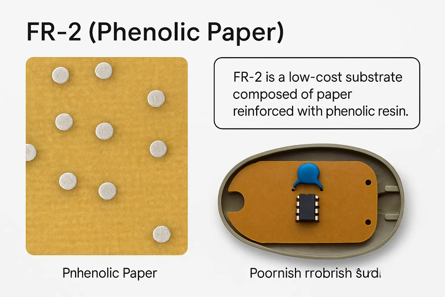
FR-2 (Phenolic Paper)
FR-2 is a low-cost substrate composed of paper reinforced with phenolic resin. It offers minimal thermal and moisture resistance, often found in disposable electronics.
Ideal for toys, low-end remote controllers, or temporary circuits. Poor mechanical durability.

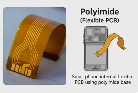
Polyimide (Flexible PCB)
Polyimide is a high-performance flexible material suitable for tight spaces and high-temperature environments. It's widely used in mobile devices and aerospace systems.
Its flexibility and heat resistance make it ideal for foldable or dynamic connection zones.


Ceramic PCBs (Alumina, BeO)
Ceramic PCBs provide excellent thermal conductivity, mechanical strength, and high-frequency stability. Materials like alumina and BeO are often used for RF and power applications.
Ideal for military electronics, microwave circuits, and IGBT driver boards.

PTFE / Teflon (e.g., Rogers RO3001)
PTFE-based materials are essential in high-speed, high-frequency circuits. Brands like Rogers offer low-loss dielectric cores perfect for RF, satellite, or radar applications.
These are costly and require precise fabrication. Ideal for advanced communication systems.


Metal Core PCB (MCPCB)
MCPCBs replace FR-4 with aluminum or copper cores to enhance thermal conductivity. Used in LED drivers, power modules, and high-current automotive electronics.
The metal base dissipates heat away from sensitive components, improving reliability.


Properties Comparison of PCB Materials
This table compares key characteristics of common PCB materials: FR-4, Polyimide, Ceramic, PTFE, and Metal Core.
| Property | FR-4 | Polyimide | Ceramic | PTFE | Metal Core |
|---|---|---|---|---|---|
| Dielectric Constant (Dk) | ~4.5 | ~4.0 | 9–10 | ~2.2 | ~1.0 |
| Tg (Glass Transition Temp) | 130–170°C | 200+°C | >250°C | ~250°C | 140–180°C |
| Flexibility | No | Yes | No | Limited | No |
| Thermal Conductivity (W/m·K) | 0.3 | 0.2 | >10 | ~0.25 | 1–2 |
| Cost | ★ | ★★★ | ★★★★★★ | ★★★★★ | ★★★ |


Application Scenarios by Material Type
Choosing the right PCB substrate depends not just on electrical properties but also on the specific use-case. Below are typical application environments matched with optimal material types and compatible IC modules.

1. General-Purpose Consumer Electronics
Recommended Material: FR-4
Why: Cost-effective and mechanically stable. Ideal for basic analog/digital circuits and prototypes.
Typical ICs: MCUs (e.g., PIC16F, STM32), voltage regulators, driver ICs.
→ Explore MCU & Power ICs for FR-4 Boards2. Wearable & Flexible Devices
Recommended Material: Polyimide
Why: Flexible, heat-resistant, and lightweight—perfect for bendable devices.
Typical ICs: Bluetooth SoCs, battery management ICs, motion sensors.
→ Browse Bluetooth SoC ICs for Flexible Circuits3. High-Frequency RF & Microwave Systems
Recommended Material: PTFE (e.g., Rogers RO3003)
Why: Ultra-low dielectric loss at GHz frequencies. Suitable for telecom and radar.
Typical ICs: RF front-ends, LNAs, high-speed transceivers.
→ View RF Front-End ICs for PTFE Boards4. High-Frequency + High Power Dissipation
Recommended Material: Ceramic
Why: Excellent heat dissipation and dielectric strength, ideal for mmWave and power RF modules.
Typical ICs: mmWave transceivers, radar SoCs, power amplifiers.
→ Find mmWave Modules Compatible with Ceramic PCBs5. High-Power LED Lighting Modules
Recommended Material: Metal Core PCBs (MCPCBs)
Why: High thermal conductivity supports LED driver circuits and high current outputs.
Typical ICs: Constant current drivers, lighting controllers, thermal protection ICs.
→ Check High Current LED Driver ICs for MCPCBCost and Manufacturing Considerations
The choice of PCB material affects not just electrical performance but also the manufacturing cost, process compatibility, and delivery time. Understanding how different materials behave during fabrication is critical for both prototyping and mass production.
1. Why Material Selection Affects PCB Cost
Materials like PTFE or Ceramic boards offer excellent electrical performance but are significantly more expensive and harder to process than standard FR-4. Advanced options often require additional steps such as multilayer pressing, microvia drilling, and specialized solder mask application.
→ Get a Custom PCB Quote2. Key Factors Impacting PCB Pricing
Below is a breakdown of how major parameters affect PCB pricing:
| Factor | Cost Trend | Notes |
|---|---|---|
| Number of Layers | ↑ Cost with more layers | 8-layer boards cost 3–4× more than 2-layer |
| Material Type | ↑ Special materials | PTFE and Ceramic can be 4–8× more expensive than FR-4 |
| Board Size & Thickness | ↑ Larger boards | Thicker boards require custom tooling |
| Surface Finish | ENIG > OSP > HASL | ENIG supports high-frequency use but is pricier |
| Precision & Features | ↑ HDI, Microvias | Advanced processing requires costly equipment |

3. Material Compatibility with Advanced Processing
Certain PCB materials are more compatible with advanced manufacturing techniques such as HDI (High-Density Interconnect), laser drilling, and via-in-pad structures. For instance, FR-4 supports most standard processes, while PTFE and ceramic substrates may require specialized equipment and incur higher costs.
If you're planning a multi-layer or complex board layout, it’s critical to choose a substrate that aligns with your routing needs and stack-up strategy. For a full understanding of how layout design impacts material selection and manufacturability, check out our detailed guide: PCB Layout Design: Step-by-Step Process, Tools, and Engineering Guidelines .
Not all materials support advanced fabrication methods. The table below highlights compatibility:
| Manufacturing Process | Compatible Materials | Remarks |
|---|---|---|
| Laser Drilling (Microvias) | FR-4, Polyimide | PTFE is hard to process |
| Copper Plating (via fill) | FR-4, Ceramic | Requires flat, even surface |
| HDI Fabrication | FR-4, Polyimide | Common in wearable and IoT PCBs |
| Thick Copper (2oz+) | Metal Core, Ceramic | Used in power applications |

4. Material Availability & Compliance
Beyond performance and cost, sourcing and compliance are equally important:
- FR-4 and Polyimide are widely available globally and supported by most PCB manufacturers.
- PTFE and Ceramic may face longer lead times in Southeast Asia and India.
- Ensure your materials meet RoHS, REACH, and UL94-V0 certifications for global compliance.

How to Identify PCB Material in Real Boards
In real-world scenarios such as reverse engineering, repair, or part substitution, identifying the PCB material is crucial. The type of substrate affects heat resistance, signal integrity, and mechanical durability. Here are the main ways to determine what material your circuit board is made of.
1. Key Identification Methods
| Inspection Area | Common Feature | What It Reveals |
|---|---|---|
| Silkscreen Markings | Codes like "FR4", "CEM-1" | Manufacturer’s material declaration |
| Color | Green, white, brown, black | Some materials like PTFE are often white |
| Flexibility | Bendable or rigid | Polyimide is flexible; FR-4 is rigid |
| Thickness & Layers | Heavier, layered boards | Metal core PCBs tend to be thicker |
| Metal Backside | Reflective aluminum or copper | Identifies MCPCB (Metal Core PCB) |
| Light Transmission | Partially or fully transparent | PI and PTFE can transmit light |
2. Visual Examples of Common PCB Materials
FR-4 (Glass Epoxy Rigid Board)

Most widely used rigid PCB substrate. Identifiable by green solder mask and "FR4" printed codes.
Polyimide (Flexible PCB)

Used in wearables and dynamic flex applications. Easily bendable and often semi-transparent under light.
Metal Core PCB (Aluminum Base)

Common in LED lighting and power electronics. Thick boards with metal reflective back.
PTFE (Teflon-based RF Substrate)

Low dielectric constant and high frequency capability. Often white and light-transmitting.
FR-2 (Phenolic Paper Board)
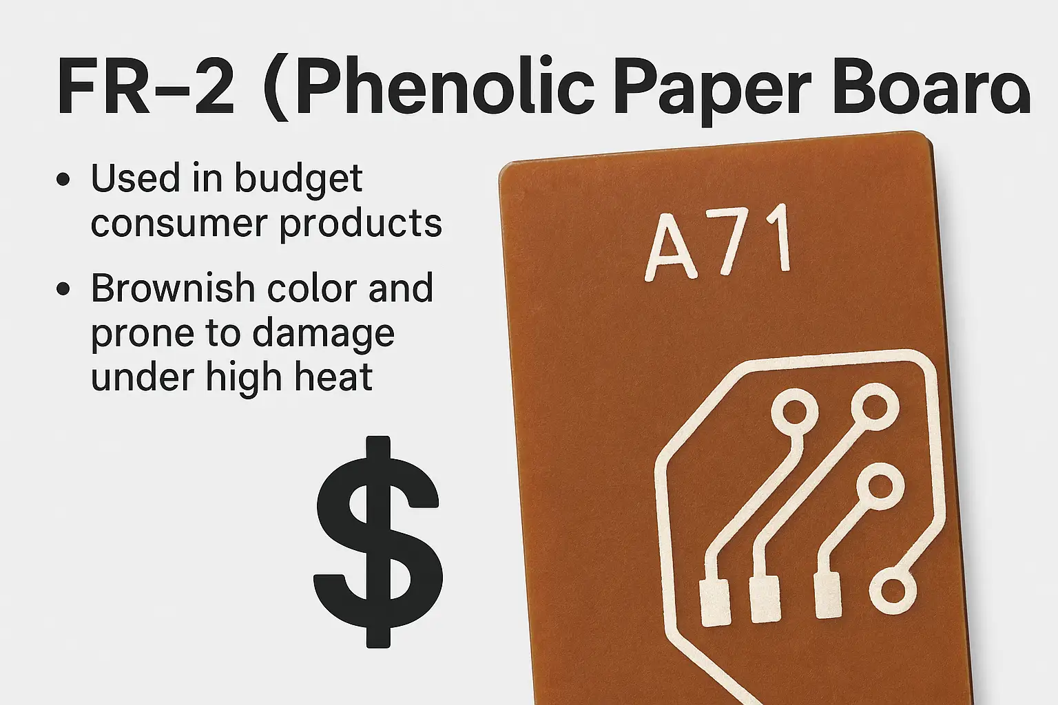
Used in budget consumer products. Brownish color and prone to damage under high heat.
3. Engineering Tips
- Mark down identified materials in the BOM for future repairs or revisions.
- If unsure, consider lab-based substrate analysis or contact the original PCB supplier.
- Use light tests and bend tests only on non-functional scrap boards to avoid damage.
Material Selection Guide for Engineers
Choosing the right PCB material is essential for ensuring performance, reliability, and cost-effectiveness. This section provides a practical guide for engineers to select PCB materials based on project requirements like frequency, thermal dissipation, flexibility, and budget.
Use-Case Based PCB Material Selector
| Design Requirement | Recommended Material | Reason | Typical IC/Application |
|---|---|---|---|
| High-frequency (5GHz+) | PTFE (Teflon) | Low dielectric loss and high stability | RF Front-End, Wi-Fi 6 Modules |
| High-frequency + Thermal Dissipation | Ceramic | High thermal conductivity and insulation | mmWave, LNA, GaN Drivers |
| Flexibility | Polyimide | Can bend and withstand high temperatures | Wearables, FPC Modules |
| Extreme Cost Sensitivity | FR-2 | Very low cost, used in disposable electronics | Alarms, Toys, Mosquito Swatters |
| Standard Industrial Use | FR-4 | Good balance between cost and performance | MCU Boards, Control Circuits |
| LED Lighting / Power | Metal Core (MCPCB) | Superior heat dissipation for high current | LED Drivers, Power Amplifiers |

PCB Material Decision Tree
Use this decision tree to quickly determine the most appropriate PCB material for your engineering needs.

Real-World Engineering Scenarios
- “I’m designing a Wi-Fi 6 router PCB. Should I use FR-4 or PTFE?”
PTFE is preferred due to lower dielectric loss at 5GHz+ - “I need a bendable board for a wearable device.”
Use Polyimide—it’s flexible and heat-resistant - “Can I use FR-4 for high-power LED drivers?”
Not ideal. Use Metal Core PCB for efficient heat dissipation.
Common Material Selection Mistakes
| Mistake | Correct Understanding |
|---|---|
| “FR-4 fits all use cases.” | High-frequency and high-power applications require specialized materials. |
| “Flexible boards only affect shape.” | They also impact EMI shielding and impedance performance. |
| “Metal core boards are too expensive.” | They offer long-term reliability in power-intensive designs. |
Frequently Asked Questions About PCB Materials
What material are circuit boards made of?
Most PCBs are made from a combination of fiberglass-reinforced epoxy resin (FR-4) as the substrate and copper foil as the conductive layer. Additional layers include solder mask, silkscreen, and surface finish.
What is the most commonly used PCB material?
FR-4 is the most widely used PCB material due to its excellent insulation properties, mechanical strength, and affordability.
What is standard PCB material?
Standard PCB materials include FR-4 for the substrate, copper for conductive layers, and epoxy-based solder masks for protection.
What is FR-4 material?
FR-4 is a flame-retardant fiberglass laminate reinforced with epoxy resin. It offers high strength, good dielectric properties, and heat resistance, making it ideal for most PCB applications.
What is BT material for PCB?
BT (Bismaleimide-Triazine) resin is a high-performance PCB substrate material often used in multilayer and high-frequency PCBs due to its low dielectric loss and high thermal stability.
What are the raw materials for manufacturing boards?
Key raw materials include glass fiber, epoxy resin, copper foil, solder mask ink, silkscreen ink, and surface finish chemicals like ENIG or HASL.
What is the full form of PCB material?
PCB material refers to all the base and functional materials used to fabricate printed circuit boards, including insulating substrates and conductive layers.
What is the raw material of PCB board?
The base raw material is typically an epoxy resin (FR-4) combined with woven fiberglass fabric, covered with copper foil.
What is the difference between polyimide and FR-4?
Polyimide offers higher flexibility, thermal resistance, and chemical stability than FR-4, making it suitable for flexible or high-temperature PCB designs.
How to identify PCB material?
You can identify PCB material by its color, flexibility, flame-retardance code (e.g., FR-4 printed on board), or through datasheet/specifications from the manufacturer.
Submit Your BOM for Material-Specific PCB Support
Do you already have a project BOM or are planning to prototype using specific PCB materials such as FR-4, polyimide, MCPCB, or ceramic? At ERSA Electronics, we specialize in matching ICs and components based on your layout requirements, performance specs, and substrate material compatibility.
Whether you're building a high-frequency RF board with PTFE or a rugged LED lighting circuit on a metal-core PCB, our sourcing and engineering teams can recommend suitable components and equivalents across leading brands.

- Rigid FR-4 boards for general electronics
- Flexible Polyimide substrates for wearable and bendable PCBs
- Metal Core (MCPCB) for LED and power-dense layouts
- PTFE / Ceramic substrates for high-frequency or thermal designs
Attach your BOM and specify your material needs. We’ll provide optimized sourcing recommendations, suggest form-fit-function compatible parts, and help you align with RoHS, UL, and IPC manufacturing standards.

Related Articles
- ·The Significance of Memory and Storage for AI
- ·Why Memory Capacity Is a Performance Bottleneck for AI Applications
- ·HBM3 vs. HBM3E: Complete Technical Comparison for AI, HPC, and Global Component Procurement
- ·How Large Language Models Work
- ·SK Hynix & Samsung: The Unprecedented HBM Expansion Race
- ·Micron 6600 ION 245TB Redefines Data Center
- ·Why Memory and Storage Define the Next Decade
- ·How Artificial Intelligence Acquires “Knowledge”
- ·How DRAM Will Change the World
- ·Why SSD Write Cache Is Crucial for AI Applications






.png?x-oss-process=image/format,webp/resize,h_32)


