
 German
 Japanese
 Portuguese
 Korea
Korea
 Mexico
 Dutch
Dutch


What Does "F" Stand for on a PCB? Full Guide to Fuse, FB, FR, and More

Introduction – Understanding PCB Component Labels
Printed circuit boards (PCBs) form the backbone of nearly all electronic devices. Whether you're dealing with a smartwatch or an industrial power controller, each PCB is populated with dozens—sometimes hundreds—of electronic components, each serving a specific function. But with so many parts densely packed onto a small board, how do engineers and technicians identify and work with them?

That’s where alphanumeric reference designators come in.
A reference designator is a short letter-number code printed near each component on the PCB. These codes aren’t random—they follow international conventions that help engineers quickly identify what each component is. For example, "R" stands for resistor, "C" for capacitor, "Q" for transistor, and "F" typically stands for fuse. You might also come across abbreviations like "FB" for ferrite bead or "FR" in materials like FR4.
Understanding what these designators mean is critical not just for designing a PCB, but also for debugging, replacing faulty parts, and ensuring safe operation—especially when working with protection elements like fuses.
In this guide, we’ll focus specifically on the “F” label on a PCB—what it means, where it appears, and how it relates to similar markings like FB, FR, and F+ / F-.

What Does “F” Stand For on a PCB?
The letter "F" on a PCB almost always refers to a fuse—a critical component for circuit protection. Fuses are designed to “break” when electrical current exceeds a safe limit, thus preventing damage to other, more sensitive components downstream.
In most PCB designs, fuses are labeled using "F" followed by a number, such as F1, F2, and so on. These numbers help engineers identify individual fuses on the silkscreen layer, in schematics, and during assembly or troubleshooting.
Fuses may appear in a variety of form factors, including:
- Surface-mount (SMD) resettable fuses
- Axial or radial leaded cartridge fuses
- Blade-style fuses for higher current applications

In schematics or component lists (BOM), you might also encounter the label “FU”, which stands for Fuse Unit. This is especially common in IEC-compliant drawings and older international circuit design standards. Functionally, “FU1” is equivalent to “F1” in most modern notations.

Key Takeaways:
- “F” = Fuse: A protective device that interrupts overcurrent conditions.
- Labeled as F1, F2, etc. on PCB silkscreens and layouts.
- “FU” = Fuse Unit: An alternate reference format commonly used in schematics and BOMs.
Other Common "F" Markings on a PCB
While “F” most commonly stands for a fuse on a PCB, it may also appear in other contexts that are less obvious but still relevant for engineers and technicians. Below are three common—but often overlooked—“F” prefixes found in PCB design and labeling.
FB = Ferrite Bead
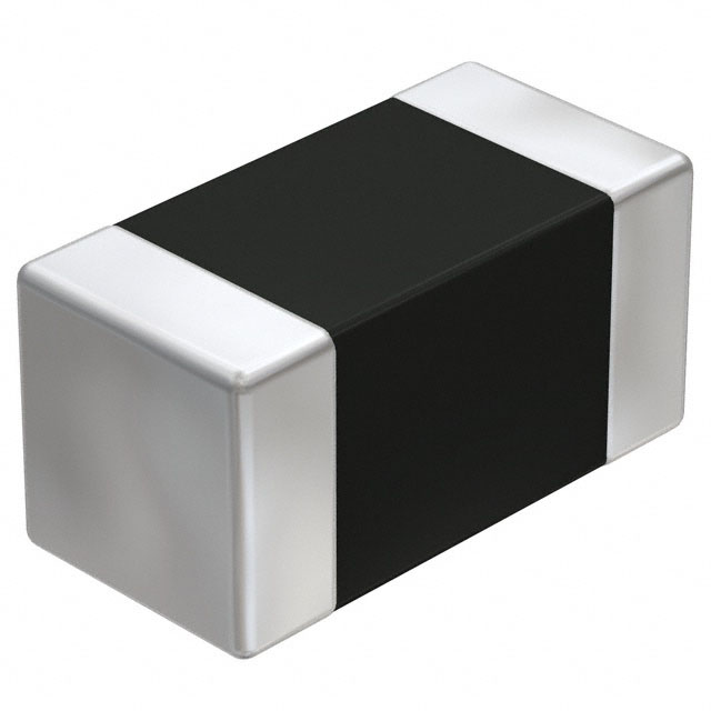
The label “FB” stands for ferrite bead, a passive component used to suppress high-frequency noise in electronic circuits. Ferrite beads are often placed on power lines, USB ports, and signal traces to prevent electromagnetic interference (EMI).
On the PCB silkscreen, ferrite beads are marked as FB1, FB2, etc., and may look similar to inductors but function differently—they are optimized for high-frequency filtering rather than energy storage.
Typical use cases include:
- Power line noise suppression
- Filtering USB or HDMI lines
- Blocking RF interference in analog/digital crossover circuits

FR = Flame Retardant (e.g., FR4)
The abbreviation “FR” refers to the flame retardant standard for PCB substrates. The most common is FR4, where “FR” stands for Flame Retardant and “4” refers to the material grade classification.
FR4 is a glass-reinforced epoxy laminate widely used in PCB manufacturing due to its:
- High mechanical strength
- Excellent insulation resistance
- Flame resistance (UL94V-0 rating)
You’ll often see “FR4” printed on the bottom layer of a PCB or listed in the board specifications.

F+ / F- = Filament Terminals
In rare cases, especially with older display modules such as VFDs (Vacuum Fluorescent Displays), the labels F+ and F− may appear. These represent filament terminals that supply current to heat the cathode filament inside the display tube.
Though uncommon in modern PCBs, these designations may still be encountered in:
- Legacy industrial control displays
- VFD-based audio equipment
- Restoration of vintage consumer electronics

PCB Reference Designator Chart
To help engineers, technicians, and electronics hobbyists quickly interpret component labels on circuit boards, we've compiled a printable PCB Reference Designator Chart. This cheat sheet outlines the most commonly used alphanumeric codes and what each represents on a silkscreen or schematic.
These standardized designators follow global conventions—used across CAD tools, BOMs, and PCB fabrication documentation.

| Designator | Component |
|---|---|
| F | Fuse |
| R | Resistor |
| C | Capacitor |
| L | Inductor |
| Q | Transistor |
| U | Integrated Circuit (IC) |
| FB | Ferrite Bead |
| FR | Flame Retardant Material |
| J | Jack / Connector |
| PS | Power Supply |
📥 Download the Cheat Sheet
Curious how these reference designators are implemented during real PCB layout design? Learn how to place, route, and label components correctly in our step-by-step guide: PCB Layout Design: Tools, Process, and Engineering Best Practices .
Download: PCB Designator Chart
Looking for a quick-access reference to identify components on your circuit board? We’ve created a downloadable PCB Reference Designator Chart that includes the most common codes like:
- F – Fuse
- R – Resistor
- C – Capacitor
- Q – Transistor
- U – Integrated Circuit (IC)
- ...and more
This chart is perfect for engineers, repair technicians, students, and BOM reviewers. Use it in your workspace, training documents, or electronics troubleshooting guides.

📥 Download the Chart

Related Articles
- ·The Significance of Memory and Storage for AI
- ·Why Memory Capacity Is a Performance Bottleneck for AI Applications
- ·HBM3 vs. HBM3E: Complete Technical Comparison for AI, HPC, and Global Component Procurement
- ·How Large Language Models Work
- ·SK Hynix & Samsung: The Unprecedented HBM Expansion Race
- ·Micron 6600 ION 245TB Redefines Data Center
- ·Why Memory and Storage Define the Next Decade
- ·How Artificial Intelligence Acquires “Knowledge”
- ·How DRAM Will Change the World
- ·Why SSD Write Cache Is Crucial for AI Applications





.png?x-oss-process=image/format,webp/resize,h_32)


