
 German
 Japanese
 Portuguese
 Korea
Korea
 Mexico
 Dutch
Dutch


STMicroelectronics
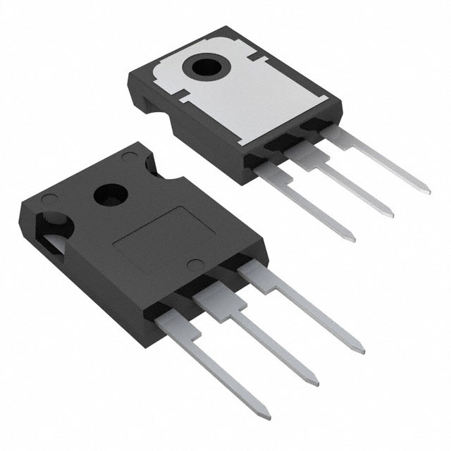
STW35N60DM2

Why Choose Us?
Professional Platform
B2B & B2C purchasingDelivery at full speed
1-2 days deliveryWide variety
Original manufacturers365 days guarantee
Responsible quality
.png)


Tech Specifications
STW35N60DM2 Description
STW35N60DM2 is a high voltage N-channel MOSFET transistor manufactured by STMicroelectronics. It is designed for use in a variety of power electronic applications, including motor control, power supplies, and energy management systems.
Description:
The STW35N60DM2 is an N-channel enhancement mode field-effect transistor (MOSFET) with a voltage rating of 600V and a continuous drain current (Id) of 35A. It is available in a TO-220 package, which is a popular and compact package for power transistors.
Features:
- High voltage rating: The STW35N60DM2 can operate at voltages up to 600V, making it suitable for high voltage applications.
- High current capability: With a continuous drain current of 35A, the STW35N60DM2 can handle high current loads.
- Low on-state resistance (RDS(on)): The STW35N60DM2 has a low on-state resistance, which minimizes power dissipation and improves efficiency.
- Fast switching: The MOSFET has a fast switching time, making it suitable for high-frequency applications.
- Robust design: The STW35N60DM2 is designed to withstand high voltage and current transients, making it suitable for use in demanding power electronic applications.
Applications:
The STW35N60DM2 can be used in a variety of power electronic applications, including:
- Motor control: The MOSFET can be used in motor control circuits to switch high currents and control motor speed.
- Power supplies: The STW35N60DM2 can be used in power supply circuits to regulate voltage and current.
- Energy management systems: The MOSFET can be used in energy management systems to control the flow of power in renewable energy systems, such as solar panels and wind turbines.
- Battery management systems: The STW35N60DM2 can be used in battery management systems to control the charging and discharging of batteries.
- Inverters: The MOSFET can be used in inverter circuits to convert DC power to AC power.
In summary, the STW35N60DM2 is a high voltage, high current N-channel MOSFET transistor that is suitable for use in a variety of power electronic applications. Its robust design and fast switching capabilities make it an ideal choice for demanding power electronic applications.
FAQ
| Quantity | Unit Price | Ext. Price |
|---|---|---|
| 1+ | $5.96400 | $5.96 |
| 10+ | $5.07943 | $50.79 |
| 30+ | $4.55315 | $136.59 |
Not available to buy online? Want the lower wholesale price? Please Send RFQ to get best price, we will respond immediately


.png?x-oss-process=image/format,webp/resize,h_32)


