
 German
 Japanese
 Portuguese
 Korea
Korea
 Mexico
 Dutch
Dutch


What is ADC resolution / ENOB?

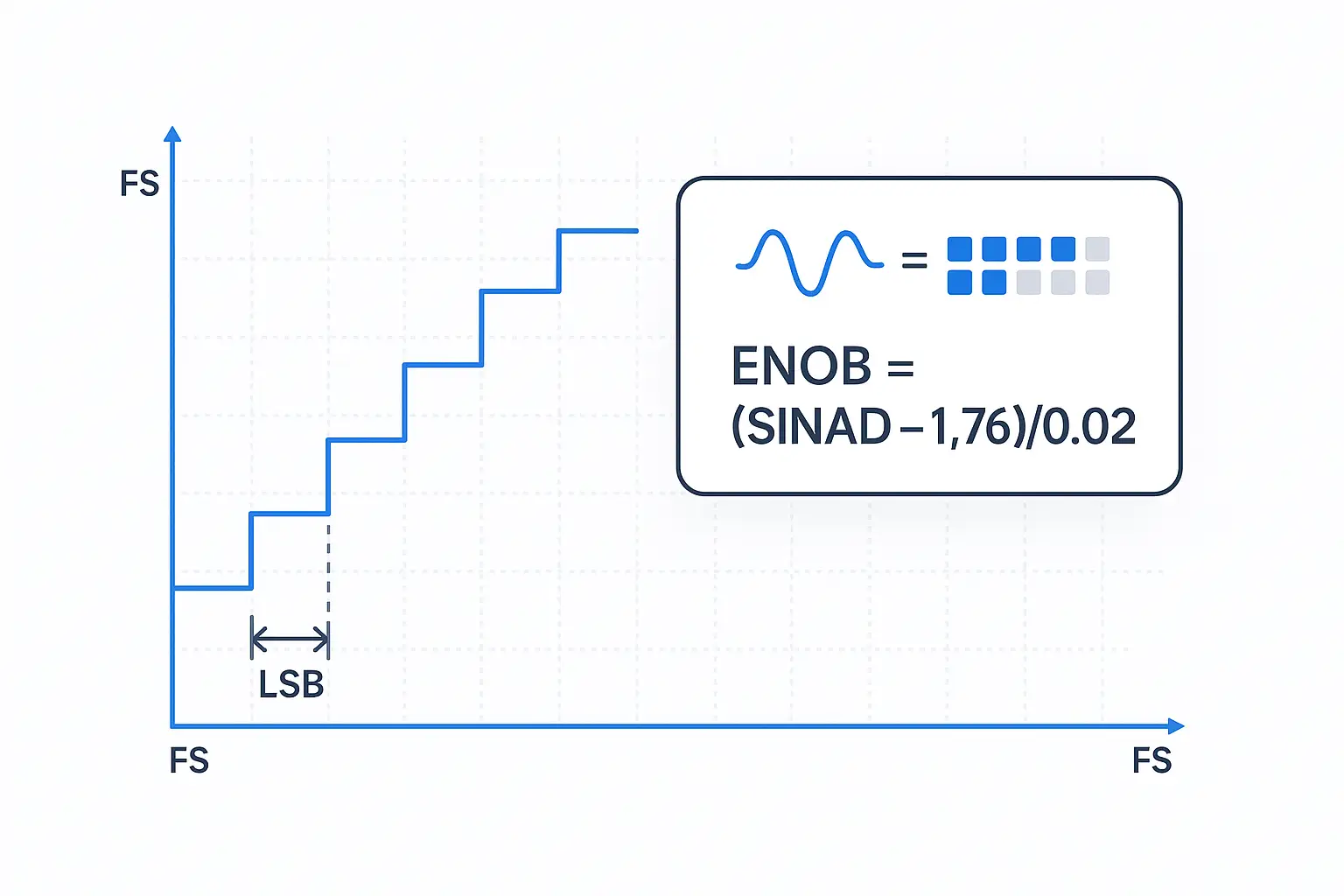
Analog to digital converter resolution describes nominal bit depth: N bits produce 2N output levels and a step size (LSB) of Full-Scale / 2N. That is not the same as real-world accuracy. ENOB meaning is the “usable bits” once noise and distortion are included; in practice you compute ENOB from SINAD, preferably not just SNR: ENOB = (SINAD − 1.76) / 6.02 (SNR can approximate but excludes harmonics). Start with the next section for quick LSB intuition and 10-/12-/24-bit examples (including why 1024 and 4096 show up). Then see how to measure ENOB with a coherent FFT and how to improve it via reference hygiene, front-end drive, anti-alias filtering, and oversampling. Want a refresher on What is an ADC? Jump to the hub. Need the Hub’s Resolution overview? Open it here.
Resolution & LSB
This section explains analog to digital converter resolution: how many discrete codes you get and how fine each step (LSB) is—before we account for real-world effects with ENOB in the next sections.
Levels = 2N · LSB = Full-Scale / 2N. For single-ended ranges, Full-Scale (FS) is approximately the reference voltage (FS ≈ Vref); for bipolar ranges, use the full span (FS = Vref-span, e.g., −Vref…+Vref). This is the core ADC resolution formula and the practical voltage resolution formula for step size.
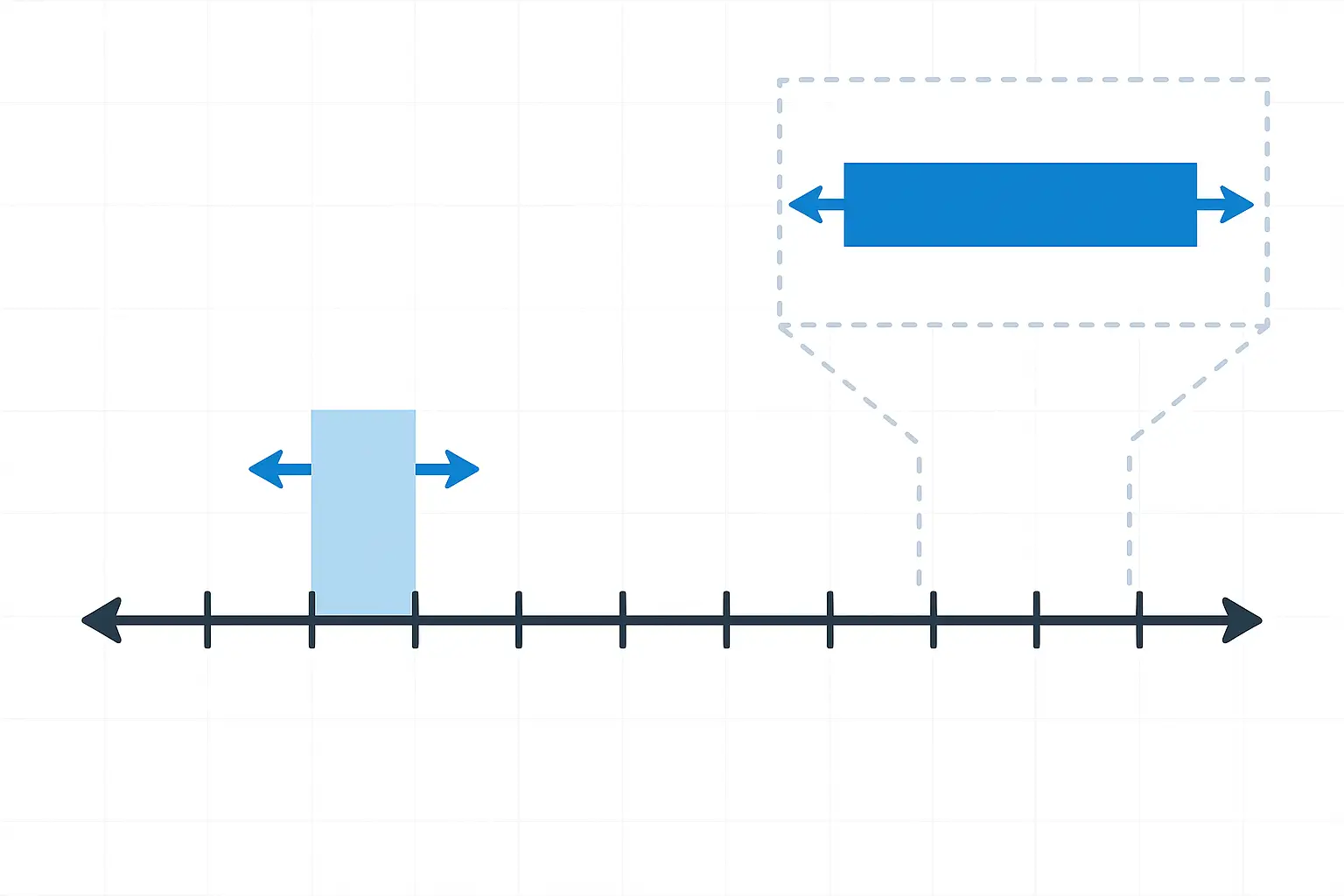
Per-code step as a fraction of full-scale: 10-bit ≈ 0.098% FS (1/1024), 12-bit ≈ 0.024% FS (1/4096), 16-bit ≈ 0.0015% FS (1/65536). These numbers help with “how to select ADC resolution”; real accuracy will be set by ENOB later.
10-bit (3.3 V single-ended) → 210 = 1024 levels; LSB ≈ 3.3 / 1024 = 3.22 mV. (also answers “what is 1024 in ADC”)
12-bit (3.3 V single-ended) → 4096 levels; LSB ≈ 3.3 / 4096 = 0.805 mV. (also answers “what is 4096 in ADC” and “what does 12-bit mean”)
24-bit (3.3 V single-ended) → 16,777,216 levels; LSB ≈ 3.3 / 16,777,216 ≈ 0.197 µV (nominal).
How to select ADC resolution (repeatable, 3 steps):
- Start from allowable input error → map to LSB with FS / 2N → get the minimum N.
- Check bandwidth/latency budget. If averaging/OSR is allowed, you can trade rate for bits.
- Match architecture: low deterministic latency → SAR; highest nominal bits at low bandwidth → delta-sigma (see ADC Types).
- Bipolar vs single-ended scaling and divider choices affect FS; verify against sensors’ ranges (Front-End & Vref).
- Vref tolerance and drift can dominate your effective step size; decouple locally and keep grounds short (Front-End & Vref).
- Data path width and link rate must carry bits × channels × fs; budget throughput early (Interfaces later on this page).
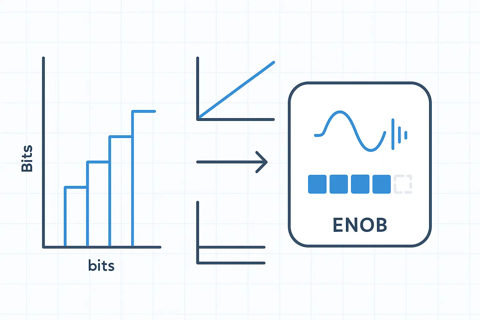
From Resolution → ENOB
Nominal resolution sets step size, but ENOB tells you how many bits you can actually trust in practice.
Ideal SNR for a full-scale sine is approximately 6.02·N + 1.76 dB.
SNR excludes harmonics (noise only). THD measures harmonics. SINAD includes noise + distortion. Prefer ENOB from SINAD for realistic, conservative “usable bits”.
ENOB quantifies usable bits: ENOB = (SINAD − 1.76) / 6.02. You can approximate with SNR, but prefer SINAD because it accounts for harmonic distortion. This is the practical ENOB meaning.
Example: if SINAD = 72 dB then ENOB ≈ (72 − 1.76) / 6.02 ≈ 11.7 bits. This is also the starting point for how to calculate ADC accuracy: convert ENOB into equivalent input noise or a fraction of full-scale.
ENOB vs effective resolution: often treated as synonyms. Some vendors define “effective resolution” from RMS noise only (code spread), while ENOB uses SINAD. Always check the datasheet’s definition.
- Comparability: ENOB lets you compare real performance across parts and configurations, not just nominal bits.
- Frequency sensitivity: at higher input frequencies, jitter-limited SNR pulls ENOB down—fix bandwidth, filtering, and clock quality first.
- Whole-chain reality: reference noise, front-end drive/settling, layout, and linearity convert ideal SNR into a lower SINAD (hence fewer usable bits).
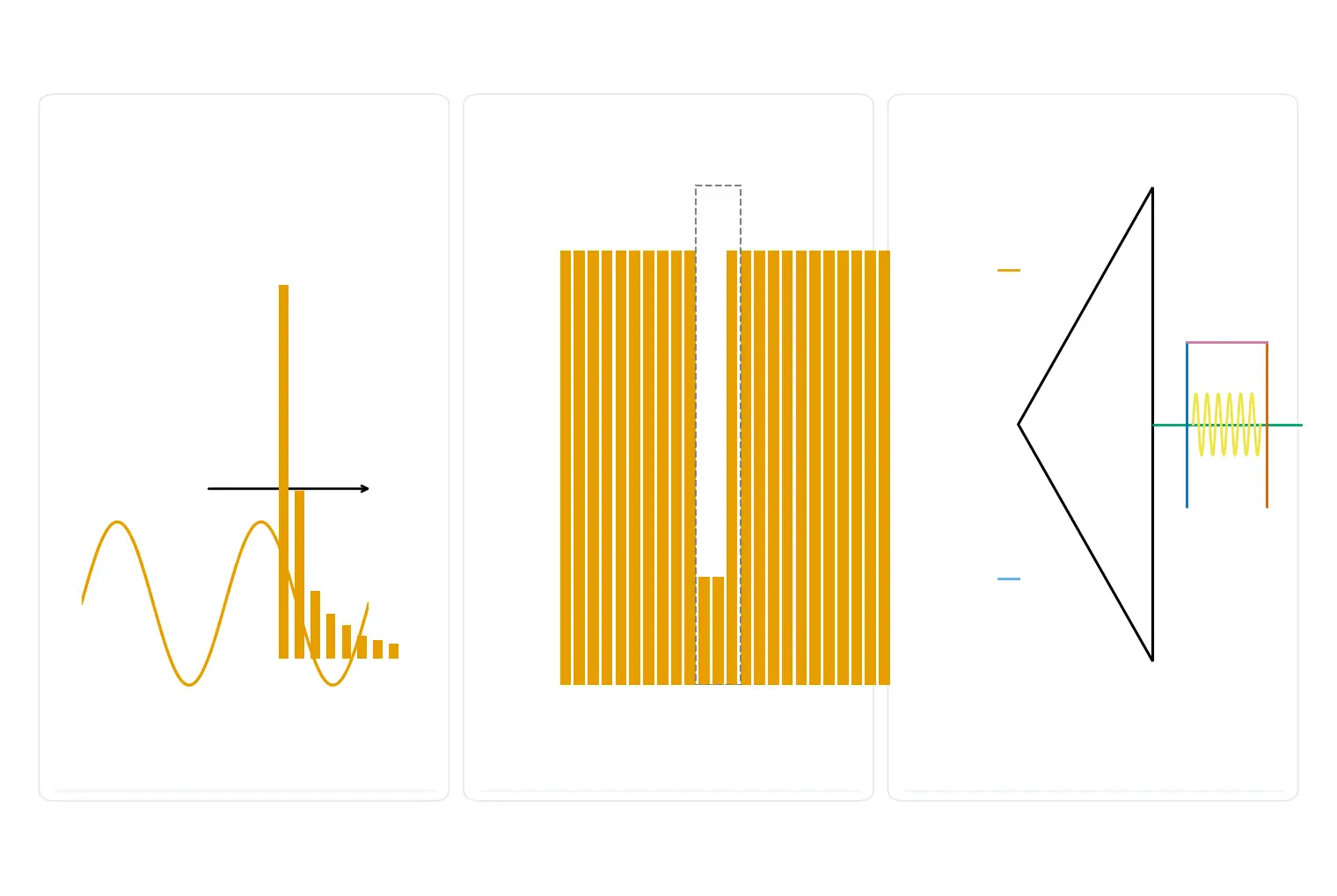
What kills ENOB
ENOB falls when noise, distortion, or timing errors dominate. Here is how to improve ADC resolution in practice—by removing the four most common ENOB killers and routing to the right deeper guides.
Reference & Grounds
Vref noise and ripple couple straight into codes; ground bounce and long return paths turn into visible code jitter.
Action: local decoupling (10 µF ∥ 0.1 µF), partitioned grounds with a single tie, short returns, and Kelvin sensing of the reference node.
Read more: Front-End & Vref →Drive & Source Impedance (incl. MUX)
The ADC’s sample capacitor must settle within the aperture; high source impedance or a weak driver raises noise and distortion. Multiplexing reduces effective sample rate and increases code scatter.
Action: buffer or lower source impedance, add RC anti-alias limit, extend acquisition time or slow the MUXed scan as needed.
Read more: Front-End & Vref →Clock Jitter & Aliasing
Jitter-limited SNR obeys SNRjitter ≈ −20·log10(2π·fin·σj): higher input frequency makes ENOB more sensitive to time noise. Unfiltered out-of-band energy folds back and further reduces SINAD.
Action: use a low-phase-noise clock, clean its rails, and set a proper anti-aliasing cutoff/order; keep noisy USB/PLL domains isolated.
Read more: Anti-Aliasing & Jitter →Linearity (INL/DNL & Missing Codes)
Nonlinearity converts ideal SNR into lower SINAD, directly cutting ENOB. Missing codes and non-monotonic behavior show up in a code-density histogram.
Action: run a density test, improve symmetry and drive linearity, or choose parts with tighter linearity specs.
Read more: Errors & Linearity →How accurate is a 12-bit ADC? It depends on ENOB: nominal bits set a ceiling, but the maximum resolution of an ADC you actually realize is limited by reference/grounding, drive/settling, jitter/aliasing, and linearity—measure, then fix these to raise ENOB.
Measure ENOB
Use a coherent sine FFT for the primary number, and validate loss sources with code-density and a DC-noise quick check—this covers how to measure ENOB, how to calculate ENOB, and the first step of how to calculate ADC accuracy.
A. Coherent sine FFT (recommended)
- Choose tone & amplitude: near full-scale but not clipping (−0.5 to −1 dBFS); avoid front-end saturation.
- Coherent sampling: pick integer cycles k and points N so
k/N = f_in/f_s. If exact coherence isn’t possible, use a Hann/Blackman window. - Acquire & window: set f_s and record length N (≥65k preferred); apply the chosen window.
- Compute FFT & bins: exclude DC and the fundamental; within Nyquist, sum noise + harmonics to get SINAD.
- Convert to ENOB:
ENOB = (SINAD − 1.76) / 6.02. Prefer SINAD; SNR is only an approximation.
Notes: clean out-of-band junk (anti-alias filter), keep the clock and rails quiet, and make the record long enough; reference/grounds must be stable.
B. Code density (histogram)
Sweep a slow ramp or triangle across the full scale and build a code density histogram. Flatness and holes reveal DNL and missing codes; such nonlinearity lowers SINAD compared with ideal SNR and explains ENOB loss.
C. DC-noise (quick estimate)
Short the input or bias it to mid-scale, record a static code stream, and compute the RMS code width to estimate effective bits. Treat this as a quick health check—the FFT/SINAD method remains the primary reference.
Convert ENOB to equivalent input noise for intuition: V_noise_rms ≈ FS / (2^ENOB · √12) (single-ended FS ≈ Vref; bipolar use FS = Vref-span).
Oversampling / OSR & Averaging
If you can spare bandwidth or throughput, oversampling adc and averaging can convert rate into ENOB—up to the limits set by noise correlations.
OSR is defined as OSR = fs / (2·BW). Under a white, uncorrelated-noise assumption, the effective bit gain follows Δbits ≈ 0.5·log2(OSR), so 2× ≈ +0.5 bit, 4× ≈ +1 bit, 8× ≈ +1.5 bits, and 16× ≈ +2 bits. This is an upper bound with ideal averaging/filtering.
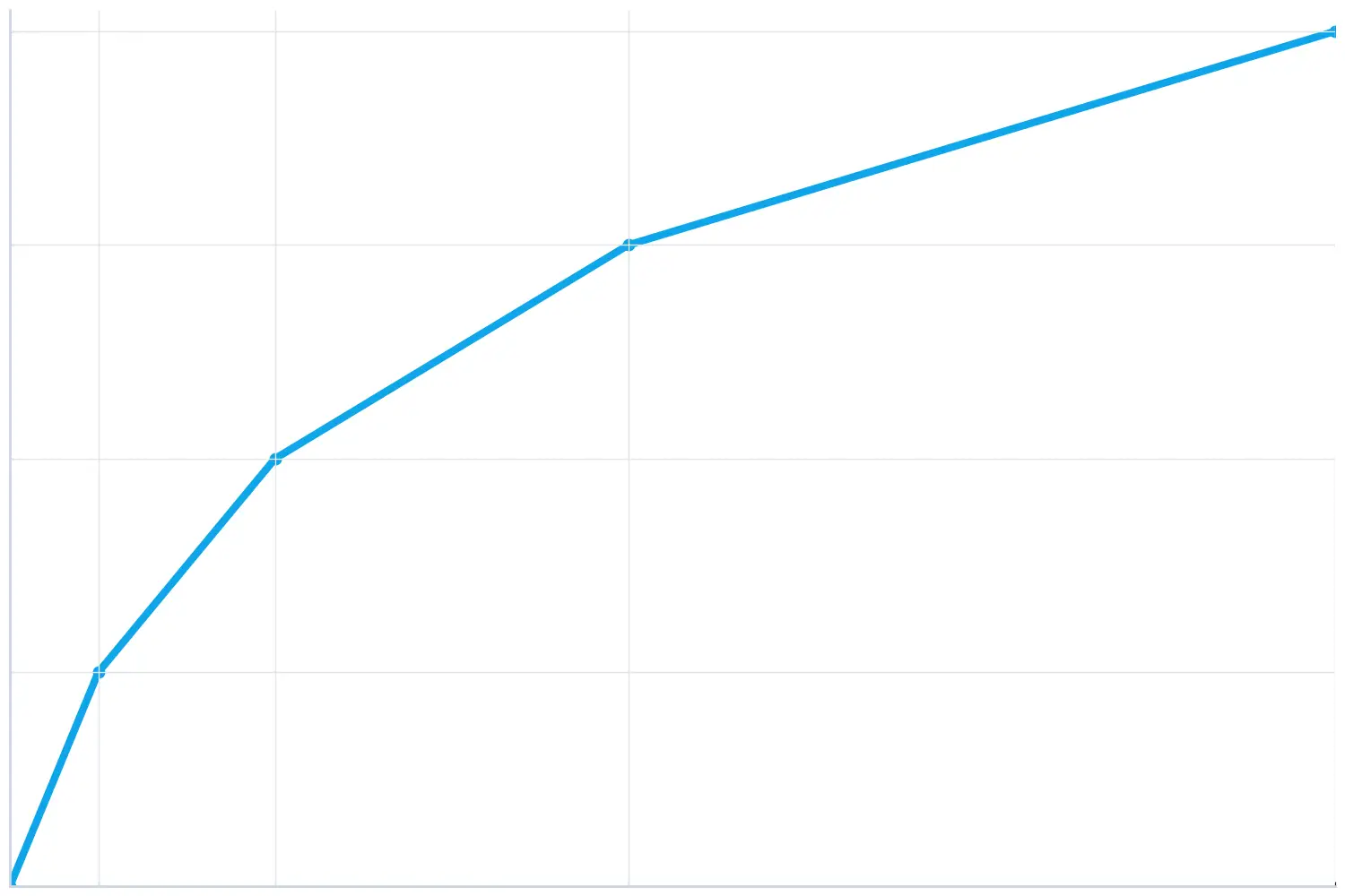
Costs: narrower bandwidth, higher latency, lower throughput, and extra compute/storage for decimation. Limits: correlated noise (reference ripple, supply hum, 1/f, EMI) and tone leakage/aliasing reduce the gain. Delta-sigma ADCs further use noise-shaping beyond the simple 0.5·log2(OSR) rule (see ADC Types).
- If averaging is allowed: pick OSR so that Δbits meets your ENOB target; implement decimation (FIR/IIR) consistent with passband ripple and group delay.
- If OSR doesn’t help: first fix Vref cleanliness, front-end drive/settling, and clock/jitter—averaging cannot remove correlated or deterministic errors.
- Verify gains: confirm with the FFT/SINAD path (Section 5) and check there is no alias contamination.
Decision Helpers: How to select ADC resolution
Use this three-step path to pick a starting bit depth, then refine with ENOB and OSR realities. This directly answers how to select ADC resolution for small-batch bring-up.
Step 1 — Allowable error → LSB → starting N
Map your allowable input error to LSB with LSB = FS / 2N. For single-ended ranges, FS ≈ Vref; for bipolar, use FS = Vref-span.
Micro-example: 3.3 V full-scale, allow 2 mV error → 3.3/0.002 ≈ 1650 codes → N ≥ log₂(1650) ≈ 10.7 → start at 12-bit. This is a nominal starting point; real accuracy follows ENOB.
Step 2 — Bandwidth/latency → OSR & averaging?
If bandwidth or latency can be traded, oversample/average to turn rate into effective bits: Δbits ≈ 0.5·log₂(OSR) (2× ≈ +0.5 bit, 4× ≈ +1 bit, 8× ≈ +1.5 bits, 16× ≈ +2 bits). Upper-bound assumes white, uncorrelated noise.
If you can’t slow down, fix correlated errors first (reference cleanliness, front-end drive/settling, clock/jitter); averaging won’t remove them.
Step 3 — System budget → pick architecture
- Check Vref purity, input drive/source impedance, clock/jitter, channels × fs throughput, package, and power.
- SAR: low, deterministic latency; easy multi-channel; broad availability.
- Delta-Sigma: highest nominal bits at low bandwidth; accepts group delay.
- Pipeline: high-speed DAQ/IF/imaging; Flash for ultra-low latency triggers.
The maximum resolution of ADC you actually realize is limited by ENOB, not just nominal bits—delta-sigma devices often list 24-bit, but usable bits depend on rate and noise conditions.
Quick Table
Note: Ideal SNR is for a full-scale sine; actual accuracy follows ENOB.
FAQ
What is ADC resolution and step size?
What is the resolution of a 10-bit ADC? / What is 1024 in ADC?
What is 12-bit resolution / What is 4096 in ADC?
What is the resolution of a 24-bit ADC?
How accurate is a 12-bit ADC?
How do you calculate ENOB?
Why is ENOB important? / What is SNR vs THD in ADC?
How to improve ADC resolution / increase ENOB?
Send your specs or BOM and get three safe options in 48 hours—each with indicative lead time, price range, and basic front-end/Vref notes.
Cut-Tape / Partial Reel / AEC-Q available.

Related Articles
- ·HBM3 vs. HBM3E: Complete Technical Comparison for AI, HPC, and Global Component Procurement
- ·How Large Language Models Work
- ·SK Hynix & Samsung: The Unprecedented HBM Expansion Race
- ·Micron 6600 ION 245TB Redefines Data Center
- ·Why Memory and Storage Define the Next Decade
- ·How Artificial Intelligence Acquires “Knowledge”
- ·How DRAM Will Change the World
- ·Why SSD Write Cache Is Crucial for AI Applications
- ·DRAM Product, Technology & Application Guide
- ·HBM4 compared to HBM4E


.png?x-oss-process=image/format,webp/resize,h_32)


