
 German
 Japanese
 Portuguese
 Korea
Korea
 Mexico
 Dutch
Dutch


STMicroelectronics
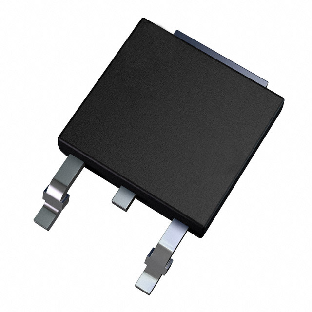
STD10N60M2

Why Choose Us?
Professional Platform
B2B & B2C purchasingDelivery at full speed
1-2 days deliveryWide variety
Original manufacturers365 days guarantee
Responsible quality
.png)


Tech Specifications
STD10N60M2 Description
STMicroelectronics' STD10N60M2 is a high-performance N-channel MOSFET (Metal-Oxide-Semiconductor Field-Effect Transistor) designed for use in a wide range of applications. Here's a description of the model, its features, and potential applications:
Model Description:
The STD10N60M2 is an N-channel enhancement mode field-effect transistor with a logic level gate. It is designed to provide high efficiency and fast switching in various power electronic applications.
Features:
-
High Voltage and Current Ratings: The STD10N60M2 is rated for a maximum drain-source voltage (VDS) of 600V and a continuous drain current (ID) of 10.5A (Tc = 25°C), making it suitable for high-power applications.
-
Logic Level Gate: The device features a logic level gate, which allows it to be easily driven by logic signals from microcontrollers or other digital circuits.
-
Low On-State Resistance (RDS(on)): With a typical RDS(on) of 0.55 ohms (at VDS = 10V, ID = 4.3A), the STD10N60M2 offers low conduction losses, improving overall system efficiency.
-
Fast Switching Characteristics: The device has a low gate charge (Qg) and a fast switching time, which makes it suitable for high-frequency applications.
-
Robustness: The STD10N60M2 is designed with a robust construction, including an integrated diode for protection against reverse-voltage transients.
-
Thermal Performance: The device has a low thermal resistance (RθJC) of 85°C/W, which helps in efficient heat dissipation and ensures reliable operation in various thermal environments.
-
Package Options: The STD10N60M2 is available in a variety of packages, including TO-220 and DPAK, to suit different application requirements.
Applications:
-
Motor Control: The STD10N60M2 is suitable for use in motor control applications, such as brushless DC (BLDC) motor drivers and AC motor speed controllers.
-
Power Supplies: The device can be used in power supply applications, including switching power supplies (SMPS) and power factor correction (PFC) circuits.
-
Inverters: The STD10N60M2 is suitable for use in DC-AC inverters, such as those used in renewable energy systems and uninterruptible power supplies (UPS).
-
Battery Management Systems: The MOSFET can be used in battery management systems for electric vehicles (EVs) and energy storage systems, where high efficiency and fast switching are crucial.
-
Industrial Automation: The device can be used in various industrial automation applications, such as robotic control systems and programmable logic controllers (PLCs).
-
Telecommunications: The STD10N60M2 can be used in telecommunications equipment, such as power supplies and signal conditioning circuits.
-
LED Lighting: The MOSFET is suitable for use in LED lighting applications, including streetlights and indoor lighting systems, where high efficiency and fast switching are important.
The STD10N60M2 is a versatile and high-performance MOSFET that can be used in a wide range of power electronic applications, offering high efficiency, fast switching, and robust performance.
FAQ
| Quantity | Unit Price | Ext. Price |
|---|---|---|
| 1+ | $0.85885 | $0.86 |
| 10+ | $0.70800 | $7.08 |
| 30+ | $0.63257 | $18.98 |
| 100+ | $0.55715 | $55.72 |
| 500+ | $0.51257 | $256.28 |
Not available to buy online? Want the lower wholesale price? Please Send RFQ to get best price, we will respond immediately


.png?x-oss-process=image/format,webp/resize,h_32)


